It may have been the 5V regulator on the SG4 overheating and going into thermal shut-down. It will dissipate a lot more heat if powered from 24VDC than if powered from 12V. If the supply is higher than 12V, the regulator should have a heat sink; it may need to be mounted on the back side of the PCB or remote mounted to do this.
It may have been the 5V regulator on the SG4 overheating and going into thermal shut-down. It will dissipate a lot more heat if powered from 24VDC than if powered from 12V. If the supply is higher than 12V, the regulator should have a heat sink; it may need to be mounted on the back side of the PCB or remote mounted to do this.
I use a DC/DC converter to step it down to 12V. It could be the DC/DC converter resetting. Will look into it when I have time to spare in a week or two.
Hi InSides,
Take a look at MyUS.com to consolidate a bunch of stuff into one shipment to you. It may very well be an answer to shipping costs. I saved more than $100 doing it this way. I am fortunate, a friend has this facilty already and made it much easier to get the AA motors and v1.03 chips.
Regards,
Kevin
Saya lebih suka menggunakan Viabox. saya rasa Viabox lebih baik. selain harganya lebih murah, pelayanannya juga cepat. saya juga bisa minta untuk dikirimkan gambar produk tanpa dikenakan biaya sedikitpun.

English only please.
I prefer to use Viabox. I think a better Viabox. Besides being cheaper, the Ministry is also fast. I could also ask for the delivered product images at no cost at all
Hi Pyramid,
I'd like to ask a question regarding the SG-4 rotary encoder implementation. I've bought the Arduino rotary encoder from local store. I realized there's only 2 pull up resistors installed, (its no mistake, the rest of the stock were all the same) 10k resistor at the switch which was missing/not installed. I did some research and referring to your build pics, I found that yours have 10k switch pull up resistor on board (total 3). I guessed it should be there since I deduced that you provided 3 resistor space on the pcb. What I did was solder the missing 10k resistor on the Arduino encoder pcb to complete it and omit any on the Phoenix encoder pcb later on. Is the 10k pull up resistor for the switch necessary and what may happen if its missing?
I'd like to ask a question regarding the SG-4 rotary encoder implementation. I've bought the Arduino rotary encoder from local store. I realized there's only 2 pull up resistors installed, (its no mistake, the rest of the stock were all the same) 10k resistor at the switch which was missing/not installed. I did some research and referring to your build pics, I found that yours have 10k switch pull up resistor on board (total 3). I guessed it should be there since I deduced that you provided 3 resistor space on the pcb. What I did was solder the missing 10k resistor on the Arduino encoder pcb to complete it and omit any on the Phoenix encoder pcb later on. Is the 10k pull up resistor for the switch necessary and what may happen if its missing?
Hi Pyramid,
I'd like to ask a question regarding the SG-4 rotary encoder implementation. I've bought the Arduino rotary encoder from local store. I realized there's only 2 pull up resistors installed, (its no mistake, the rest of the stock were all the same) 10k resistor at the switch which was missing/not installed. I did some research and referring to your build pics, I found that yours have 10k switch pull up resistor on board (total 3). I guessed it should be there since I deduced that you provided 3 resistor space on the pcb. What I did was solder the missing 10k resistor on the Arduino encoder pcb to complete it and omit any on the Phoenix encoder pcb later on. Is the 10k pull up resistor for the switch necessary and what may happen if its missing?
The pull-up resistors are necessary for the I & Q outputs of the rotary switch as those outputs go to the 4013 IC; without pull-ups, the circuit will not function at all. The momentary push sw output of the encoder connects directly to the Stby switch of the SG-4, which as a pull-up installed on the PCB, so technically, it is not necessary to add, but does not hurt if it is there.
The two 0.47 caps are necessary on the I & Q outputs to prevent switch bounce from causing false action of the 4013. Without them, you will get random up/down output from the 4013, no matter which way you rotate the encoder.
The two 0.47 caps are necessary on the I & Q outputs to prevent switch bounce from causing false action of the 4013. Without them, you will get random up/down output from the 4013, no matter which way you rotate the encoder.
Thank you Pyramid, appreciate your response very much.
")
I've soldered that missing 10k on the encoder, that about wrap up that area and ready to use.
Another call-out to Pyramid for such a great job on the design and development of the 4-phase sinewave generator. I populated the board this weekend and fired it up successfully. Thanks also to Twystd for the programmed chip, and rsritchey for a 3-channel amp board that I also built.
I'm a huge fan of Bill's (Phoenix) work, owning both an Eagle/Roadrunner for my Papst-powered Empire turntable project and a Falcon/Roadrunner for my VPI Scout. Despite the improvement in speed stability that the Falcon made on my Hurst-powered Scout, I'm enthusiastic about the opportunity to try the potentially better AA 3-phase BWLS motor. Certainly the motor *feels* smoother. Now I just have to get a pulley made, and a case/faceplate/switches made. plus do the alignment settings on the MA-3D amp.
This has been a fun project. I'll report back on my sound quality observations when I finish it and get a chance for some extended listening.
Thanks to all who made it possible, and especially YOU, Bill!

I've been asked recently about providing more chips and boards, I'm about to order a new batch of chips, please PM me if you're in need of single boards as well and I'll order enough to sell along with the chips. If you need 2 or more boards it works out cheaper to leave out the middle man (me) and order 3 direct from OshPark. (only for Rest of World, not US)
regards
Ralph
regards
Ralph
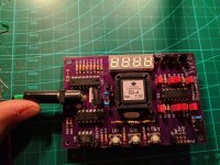
not sure what is going on with my SG4
Please forgive me I am a bit of a noob to this.
I recently assembled my board and seemed to have no problem. I put it in a case and connected it to a new power supply and I get no function. I get a display when I disconnect and reconnect a few times but it seems to be non responsive. I have replaced all components on the board except the chip. Did I fry the chip? Any suggestion would be appreciated.
Thanks in advance
Attachments
If you have a scope or frequency counter, check to see that the crystal oscillator is running (look at either side of R9 1M resistor) at 18.432 MHz.
With a DC voltmeter, check that U4 output (Reset) goes briefly (~350mSec) at power up. You can also force a reset by shorting U4 output to 5V briefly.
Check that there are no shorted or bent pins on the socket where the µP makes contact. Sometimes, the pins of the socket get bent away from the chip and do not make good contact.
Check for excessive flux on or around the pins of the µP socket, especially pin 32 and the crystal oscillator circuit. If pin 32 is grounded at reset, the chip will go into flash mode. You and add a 2.2K resistor between pin 32 and 5V to prevent this.
I do not have a scope to test the crystal but I do have a few spare to try with and all had the same problem.
I checked the output of the reset and it is a delay.
I have cleaned all the pins with contact cleaner and have no excessive flux or solder around the socket or the crystal.
I put a 2.2K resistor on pin 32 and 5v but it seems to be no change. I have tested voltage as per the instructions and am getting: U3 Pin 16: 5VDC U2 Pin 4: 8VDC
Sometimes the powerup will not bring up the display and with a few resets it will be all 8s or all 6s or sometimes 8s with the top segment missing.
About the Display LTC-2723E, is it possible to use a 4-digit 12 pin cathode alternative?
the only option I found here in Brazil, besides the 12 pin, is this one:
http://www.foryard-led.ru/pdf/fyq-4041gx_hx.pdf
Will it work?
Thanks!
the only option I found here in Brazil, besides the 12 pin, is this one:
http://www.foryard-led.ru/pdf/fyq-4041gx_hx.pdf
Will it work?
Thanks!
- Home
- Source & Line
- Analogue Source
- DIY 4 Phase Sinewave Generator for Turntable Motor Drive