Pyramid,
If I want to power the SG4 off the MK-154 amp, which filter cap should I take the 18V DC from? The one reaest the AC input or the one furthest away? As you cannot see the tracks on the board it's not obvious. I tried taking power from the furthest cap which I assumed was +18V but I suspect it may have been -18V as when I turned everything on a coil of smoke came from the MK-154, no big bang or blown rectifier though. Powering the amp separately now shows a large DC offset on the output so I may have blown something. The SG4 is still working. I've ordered another amp so I'll give it another go. Also are the 2K2 resistors on the MK-154 enough to reduce the gain or should I still use a dual gang pot? I'm in the UK, so I've got 240V mains but I'm outputting 120V dual phase. Any advice please?
Peter
Pyramid,
If I want to power the SG4 off the MK-154 amp, which filter cap should I take the 18V DC from? The one reaest the AC input or the one furthest away? As you cannot see the tracks on the board it's not obvious. I tried taking power from the furthest cap which I assumed was +18V but I suspect it may have been -18V as when I turned everything on a coil of smoke came from the MK-154, no big bang or blown rectifier though. Powering the amp separately now shows a large DC offset on the output so I may have blown something. The SG4 is still working. I've ordered another amp so I'll give it another go. Also are the 2K2 resistors on the MK-154 enough to reduce the gain or should I still use a dual gang pot? I'm in the UK, so I've got 240V mains but I'm outputting 120V dual phase. Any advice please?
Peter
You will need to take the +18VDC from the positive terminal of the filter cap that has the minus terminal connected to ground. Use an Ohm meter to verify this.
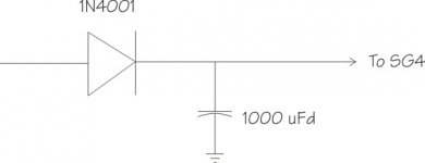
You will also need to isolate the supply going to the SG-4 with a diode and 1000uFd cap. If you don't, the SG4 will most likely never come out of reset.
You must change the resistors on the MK-154 board to 2K2, but you should also have a pot to set the levels.
The 5V regulator on the SG4 will need a heat sink if you power it from 18VDC. You can move the regulator to the back side of the PCB to make room for a heat sink or you can remotely mount it on a heat sink and run wires to the SG4.
Attachments
I should have realised about using an ohm meter, it's obvious now you've mentioned it. I have the diode and the 1000uF cap already set up. The regulator already has a large heatsink and I'll use the pot so I can test it all using loudspeakers before I connect the output transformers. Many thanks.
It's alive!
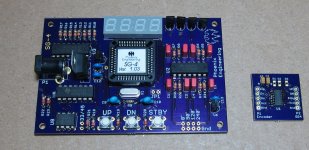
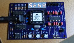
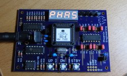
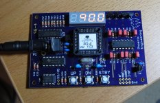
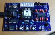
I ordered SG4 and SMD rotary encorder boards from Oshpark and programmed uProcessors from twystd and ordered the stock parts list from Mouser. Everything arrived over the last week, so I spent the morning putting things together. Pyramid's documentation was very thorough and easy to follow and everything seems to work like a charm. Thanks to both Pyramid and twystd for making this so easy to put together. I still need to get the amplifiers and transformers to finish the controller but thought I'd document this part for those interested. I've attached a few pictures showing the SG4 in operation.
If anyone is interested, I can probably spare one set of boards and one of the uPs. I'd sell these at my cost + shipping. PM if interested. Note that the uPs have the latest v1.03 software, so they're compatible with the 3 Phase BLDC project that Pyramid has been discussing in another thread.
Thanks,
---Gary
Attachments
Last edited:
I can probably spare one set of boards and one of the uPs . . .
Quick update - the extra boards and uP have been spoken for.
---Gary
The 3 phase class D amp project is completed:
http://www.diyaudio.com/forums/analogue-source/307918-3-phase-class-d-amp-diy-bldc-motor-drive.html
http://www.diyaudio.com/forums/analogue-source/307918-3-phase-class-d-amp-diy-bldc-motor-drive.html
@Pyramid,
not having yet being able to assess the power of the Anaheim motors myself (long time to have them shipped here), have you considered a multiple motor drive platform? Two, or even three motors per turntable?
I am hoping to drive a 35+ pound platter, and while I understand that synchronizing different motors might be troublesome, would you say that the SG4 can run two, or three, identical motors? Obviously, the number of amplifier channels would increase.
The SG4 would have no problem driving multiple amplifiers per phase.
Synchronizing the motors won't be a problem if driven in parallel as long as the pulleys are cut the same and the same diameter belts are used.
I doubt that you will need more than one motor to turn the platter. There may be some belt "burn out" at start up, but once the platter is up to speed, it require very little torque to maintain speed.
The SG4 would have no problem driving multiple amplifiers per phase.
Synchronizing the motors won't be a problem if driven in parallel as long as the pulleys are cut the same and the same diameter belts are used.
I doubt that you will need more than one motor to turn the platter. There may be some belt "burn out" at start up, but once the platter is up to speed, it require very little torque to maintain speed.
Much appreciated.
Living where I do makes experimentation quite difficult. I may end up using one motor, but since I am ordering from overseas, it actually is quite less expensive (in the long run) to order more motors, more boards, more uPs etc at once than to come back and do another order later on.
I was thinking of trying multiple motors but with the same belt, so at least can eliminate one hurdle.
Additionally, I would also like to experiment with building both the LM3886 amp you designed and the Class D, just to see how each performs in my application.
P.S. Just a matter of time before someone decides to do a tube amp to connect to the SG4. More expensive and more complicated, but hey - when have we in this hobby been sane.
Folks:
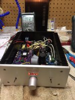
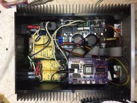
I'm cautiously excited and would appreciate a little guidance. The output voltage on my SG-4 maxes out at 91 or so volts AC. Everything else looks good to me, though something's clearly amiss. Any and all advice appreciated!
Regards,
Scott
I'm cautiously excited and would appreciate a little guidance. The output voltage on my SG-4 maxes out at 91 or so volts AC. Everything else looks good to me, though something's clearly amiss. Any and all advice appreciated!
Regards,
Scott
Attachments
Check your voltages against those in this post: http://www.diyaudio.com/forums/anal...-diy-turntable-motor-drive-5.html#post4967817
Also, what is the reduced voltage set to on the SG-4? Is the voltage higher when you first exit standby?
Good looking build BTW.
Also, what is the reduced voltage set to on the SG-4? Is the voltage higher when you first exit standby?
Good looking build BTW.
Last edited:
Pyramid:
Thanks for the quick response! I'm not at home right now but will try to get those voltages later today or tomorrow. In the meantime, one thing I failed to mention is that the voltage increased to 105VAC when I switched from 33 (60.00 hz) to 45 (80.00 hz). Also, I have not grounded the amp board (though of course the input ground does run to the SG-4 board).
Regards,
Scott
Last edited:
Pyramid:
I have doubts about whether I've properly measured VPP (and have indicated why below), but here are the measurements:
-----------------VDC------VRMS------VPP
SG4 Output___2.48____1.74_____4.98__(60 hz)
MK-154 Out__________6.06_____0.16
Output Xfmr__________91.2_____[1]
PwrXfmr-MK154_______14.74____29.5
SG4 Output___2.48____1.74_____4.98__(80 hz)
MK-154 Out__________7.00_[2]__[3]
Output Xfmr__________105.1____[1]
PwrXfmr-MK154_______14.36____28.87
[1] the two live pins on the xfrmr are tied together, as are the two neutral pins. There is 0 ohms between the two pins in each set and no voltage difference.
[2] this is a measurement of Channel R L & N; Ch L reads about 7.02
[3] I couldn't figure this measurement out given how I wired this transformer.
I'd be happy to take more measurements. If the answer is to increase the two resistors on the MK-154 board to something above 2.2k, would it be reasonable to simply pull one leg of each resistor and add a 1k resistor (for a total of 3.2k) with the understanding that I'd have to dial the 10k pot back? I have plenty of 1k resistors lying around but nothing that would easily get me to 2.8k or 2.9k.
Regards,
Scott
Pyramid:
I have doubts about whether I've properly measured VPP (and have indicated why below), but here are the measurements:
-----------------VDC------VRMS------VPP
SG4 Output___2.48____1.74_____4.98__(60 hz)
MK-154 Out__________6.06_____0.16
Output Xfmr__________91.2_____[1]
PwrXfmr-MK154_______14.74____29.5
SG4 Output___2.48____1.74_____4.98__(80 hz)
MK-154 Out__________7.00_[2]__[3]
Output Xfmr__________105.1____[1]
PwrXfmr-MK154_______14.36____28.87
[1] the two live pins on the xfrmr are tied together, as are the two neutral pins. There is 0 ohms between the two pins in each set and no voltage difference.
[2] this is a measurement of Channel R L & N; Ch L reads about 7.02
[3] I couldn't figure this measurement out given how I wired this transformer.
I'd be happy to take more measurements. If the answer is to increase the two resistors on the MK-154 board to something above 2.2k, would it be reasonable to simply pull one leg of each resistor and add a 1k resistor (for a total of 3.2k) with the understanding that I'd have to dial the 10k pot back? I have plenty of 1k resistors lying around but nothing that would easily get me to 2.8k or 2.9k.
Regards,
Scott
The output from the SG4 looks right, so I don't think there is any problem there.
The output of the MK154 looks a bit low (should be ~8.4VRMS each channel). This level should not be different for 60Hz and 81Hz either. Did you put a coupling cap between the SG4 and the pot or between the pot and the MK154? There is no need for one in either spot.
The rest looks about right, given the output of the MK154.
I don't understand your notes 1-3. When you measure VRMS, use the AC setting on a DVM or analog meter and measure the 2 pins of each output, not between R & L. Measure VPP the same way, but using an O-scope.
Pyramid:
Ahh, I completely misunderstood VPP. I don't have a 'scope.
No coupling caps were added. What might be the cause of the different outputs?
Regards,
Scott
Is the reduced output level for each speed set to max (128)?
Hi InSides,
Take a look at MyUS.com to consolidate a bunch of stuff into one shipment to you. It may very well be an answer to shipping costs. I saved more than $100 doing it this way. I am fortunate, a friend has this facilty already and made it much easier to get the AA motors and v1.03 chips.
Regards,
Kevin
Take a look at MyUS.com to consolidate a bunch of stuff into one shipment to you. It may very well be an answer to shipping costs. I saved more than $100 doing it this way. I am fortunate, a friend has this facilty already and made it much easier to get the AA motors and v1.03 chips.
Regards,
Kevin
Last edited:
- Home
- Source & Line
- Analogue Source
- DIY 4 Phase Sinewave Generator for Turntable Motor Drive