Hey Hans
Glad your back. The proof of the pudding is in eating it. And it sounds like yours taste fine. I am glad you started this thread I am learning a lot and getting new ideas in search for the holy grail.
The post about about hysteresis synchronous motor sounds interesting. Maybe a surplus place or rob from a tape machine.
Anyway looking forward to the start up and running specs .Thanks Tom
... I've been using a BLDC motor with 3 phase drive and it is head and shoulders above the Hursts:
BLDC Turntable motor
3 phase motor for turntables? I think you are onto something.
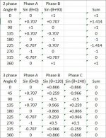
Electric power plants use 3 phase generators, and the workhorse standard for large electric motors in industry is 3 phase. Among other reasons for using 3 phase power, motors wound for balanced 3 phase will vibrate less than a 2 phase motor. 3 phases spaced 120 electrical degrees apart sum to a constant. 2 phases spaced 90 electrical degrees apart do not, and so there will be cyclical torque variation as the rotor spins. To illustrate, I attached a tabulation of the voltage sequence for each system through 1 cycle.
In a balanced 3 phase system the mechanical torque on the motor shaft is constant. In a 2 phase system there will be torque pulsation on the motor shaft, even if the sine wave is pure and the phases are separated by exactly 90 degrees.
Ray K
Attachments
In my experience, it's not as simple as you would like it to be. In theory, a 15W motor should require a little more than 15W output at the amp (allowing for 5-15% loss in the xfmr). However at start up, there will be a significant current draw due to core magnetization in the xfmr, so it might require a much larger amp to prevent oscillations or overload resulting in the amp shutting down.
At start up, the xfmr will present a very low impedance to the output of the amp. Assuming it can handle this, it will stabilize and the impedance seen by the output of the amp will be (approximately), the DC resistance of the motor coils divided by the square of the xfmr turns ratio. Calculating the turns ratio is not as straight forward as it seems: a 12V-120V xfmr does not have a 10:1 turns ratio. Most of the xfmrs will be designed for 115VAC input, but the rated output voltage is at full load. A close approximation of turns ratio would be input voltage/no load output voltage, which for a 12VAC xfmr will be ~15V so the turns ratio is closer to 7.66:1.
Your 15W motor should have windings of ~880 Ohms; using a 12V xfmr, the load presented to the amp would be ~15 Ohms and you would need to provide 15VRMS (42VPP) to get 115VAC at the output of the xfmr.
This is an oversimplification of the process and ignores losses in the xfmr, back EMF generated by the motor and parasitic components throughout, but it should be a reasonably close approximation.
Can these start up requirements be relaxed if you were to manually (use your finger) start the platter spinning?
There is always a way to improve things, but at what cost and what will be the gain.In a balanced 3 phase system the mechanical torque on the motor shaft is constant. In a 2 phase system there will be torque pulsation on the motor shaft, even if the sine wave is pure and the phases are separated by exactly 90 degrees.
Ray K
I could have bought a very expensive VPI direct drive, which probably has a BLDC 3 phase motor, the most sophisticated motor I can imagine, but I have to live with what I have.
The question is however, is it good enough to do the job ?
And the answer to my opinionis is a firm yes , when driven with a stable 2 phase steering.
My argumentation to come to this is the following:
The theoretical maximum SNR of an LP after Riaa correction is ca. 66dB-A.
I played a silent groove on a Feickert test LP and recorded the noise.
Then I played a 1kHz tone recorded at 0dB from the same test LP.
I transferred both spectra to Excel and calculated the A-weighted noise, which turned out to be -48dBr-A.
The 0db 1kHz reference measured at 16dBr +/-1dB, corrected for the scallopping loss of the Hann window, being between 0 and 2dB.
That resulted in a SNR of 64dB-A +/-1dB, very very close to the theoretical max.
So I don't see how a better motor could possibly improve on this.
Of course the noise of my phono preamp was much lower, not to interact with the measured figures.

In the figure above, I have also include the noise after doing an inverse Riaa, this being the shape of the noise as directly coming from the Cart.
Above 1kHz, noise is flat. As from 200Hz going down, noise increases with approx. 20dB/decade, but without any indication of rumble.
So to conclude, I think the used motor driven by two perfect phases is adequate for the job.
Hans
P.S. I forgot to tell that the recordings were made without any rumble filter.
Last edited:
O.K. I promised to measure the current supplied by the amplifier and to publish the results.
In my situation, the oscilator and the phase splitter are running 24/7.
When starting the turntable, I use the switch on the motor housing of the VPI to switch on the amplifiers.
As I am using a Quad 303 for the purpose, where it should be mentioned that this amp has no +/- supply, but only one supply.
To drive a speaker, a large electrolytic cap is in the output to do the necessary level shifting.
But at start up, this cap has to be loaded first to half the power supply.

That is why you see clipped signals to start with in the image above of both phases. Blue is voltage produced by the amp and red is the current that is flowing.
The voltage gradually ramps up to ca.16volt rms, and the current has one large peak in both phases, but still below 2Amp.
After this peak, current goes quite rapidly to a stable situation of 240mA rms.
Not regarding a possible phase shift between voltage and current, power is now 16V x 0.24A = 3.84 Watt per phase, or a stable 2x 3.84Watt for the stereo amp when the turntable is running, with single peaks of below 2x 2Amp at start up.
This kind of power can be supplied by every stereo amp on the market !
Since my current gear is more sophisticated, I made a fresh recording of the voltages of the two phases when the turntable is running stable, to show the quality of the signals.
Also did I record a Lissajou figure made of both signals, showing a perfect circle.

Hans
In my situation, the oscilator and the phase splitter are running 24/7.
When starting the turntable, I use the switch on the motor housing of the VPI to switch on the amplifiers.
As I am using a Quad 303 for the purpose, where it should be mentioned that this amp has no +/- supply, but only one supply.
To drive a speaker, a large electrolytic cap is in the output to do the necessary level shifting.
But at start up, this cap has to be loaded first to half the power supply.
That is why you see clipped signals to start with in the image above of both phases. Blue is voltage produced by the amp and red is the current that is flowing.
The voltage gradually ramps up to ca.16volt rms, and the current has one large peak in both phases, but still below 2Amp.
After this peak, current goes quite rapidly to a stable situation of 240mA rms.
Not regarding a possible phase shift between voltage and current, power is now 16V x 0.24A = 3.84 Watt per phase, or a stable 2x 3.84Watt for the stereo amp when the turntable is running, with single peaks of below 2x 2Amp at start up.
This kind of power can be supplied by every stereo amp on the market !
Since my current gear is more sophisticated, I made a fresh recording of the voltages of the two phases when the turntable is running stable, to show the quality of the signals.
Also did I record a Lissajou figure made of both signals, showing a perfect circle.
Hans
Hi Hans
Thanks for current draw information. Been reading all the motor/controller threads and the thing that comes up again and again is lots of ideas but little execution. You took what had modified it and came up with something that worked. Good for you!!!
In going over your notes you started with the project box to get your signal. You then split / amped / step up for the final voltage to motor.
So if we had a vpi SDS (for example) we get the sine wave and it is capable of 20 watts at 120 volts. So we take that output and split it bypass the quad amp (in your case) and the step up trans. I need the 120v here in US.
So the different variables are splitting at 16 volt vs 120 volts. Voltage losses at splitter. And probably lots of things I have not thought of.
Another option I have is I have 2 function generations I could use as bread board to see how it works if you think the signal is good enough for this application.
Thanks Tom
For what appears to be a suitable signal generator look here:-
NEW 3-Phase Sinusoidal Signal Generator Adjustable Phase 0.1?2000 Hz | eBay
The distortion levels are low, about 50~60 db down; the phases are adjustable in 1 degree steps, so you can use 2 phases 90 deg apart for a hysteresis motor or 3 phases 120deg apart for a Papst 3 phase motor as I am using for my Thorens TD124. The output is also adjustable from about 1V to 6V.
The 'power' side of the circuit will vary, depending on the motor requirements, but I am using these amps very successfully:-
100W DC 12V-24V TPA3116 Mono Channel Digital Power Audio Amplifier Board BTL Out | eBay
I like the fact that they will happily drive a 2 Ohm load, so in my case only need a 1 ohm ballast resistor between the amp and the transformer to limit the startup current.
I have no connection with either supplier except as a happy customer.
Hi Ralph,For what appears to be a suitable signal generator look here:-
NEW 3-Phase Sinusoidal Signal Generator Adjustable Phase 0.1?2000 Hz | eBay
The distortion levels are low, about 50~60 db down; the phases are adjustable in 1 degree steps, so you can use 2 phases 90 deg apart for a hysteresis motor or 3 phases 120deg apart for a Papst 3 phase motor as I am using for my Thorens TD124. The output is also adjustable from about 1V to 6V.
The 'power' side of the circuit will vary, depending on the motor requirements, but I am using these amps very successfully:-
100W DC 12V-24V TPA3116 Mono Channel Digital Power Audio Amplifier Board BTL Out | eBay
I like the fact that they will happily drive a 2 Ohm load, so in my case only need a 1 ohm ballast resistor between the amp and the transformer to limit the startup current.
I have no connection with either supplier except as a happy customer.
Interesting options that you refer to and quite affordable.
Hard to believe that you can get Amp's for £4.88 !!
However, I'm a bit cautious with digital amps because of the large high frequency content they may produce. Have you any experience with these specific examples?
But in principle all you will need on top of this for doing an experiment are two trafo's and that's it.
You can play with all parameters: amplitide, frequency and phase.
And that all for the price of less than 10% for an SDS.
Hans
Hi Tom,Hi Hans
Thanks for current draw information. Been reading all the motor/controller threads and the thing that comes up again and again is lots of ideas but little execution. You took what had modified it and came up with something that worked. Good for you!!!
In going over your notes you started with the project box to get your signal. You then split / amped / step up for the final voltage to motor.
So if we had a vpi SDS (for example) we get the sine wave and it is capable of 20 watts at 120 volts. So we take that output and split it bypass the quad amp (in your case) and the step up trans. I need the 120v here in US.
So the different variables are splitting at 16 volt vs 120 volts. Voltage losses at splitter. And probably lots of things I have not thought of.
Another option I have is I have 2 function generations I could use as bread board to see how it works if you think the signal is good enough for this application.
Thanks Tom
Thanks for your kind words.
I think the sort of solution that Ralph has proposed is the way you could follow to experiment on a very low cost base.
I'll be interested to hear from you when you have something up and running.
Hans
Marcus your post caught my eye on the hysteresis type motor so I looked it up. Seems they where use a lot on reel to reel tape decks. Did these tape decks use any special power supplies or just ac from the wall. If you where a betting man would you think you would get a better running motor with a hysteresis motor with ac from the wall or a standard synchronous motor with a controller with or without phrase control?
Thanks Tom
As far as I know, they typically used AC from the wall with a phase splitter cap. You will get better (lower torque ripple) performance from a hysteresis synchronous motor running from the AC line.
Hi All, any advice for decent Kit or PCB to control Hurst 3001-001? It is 115VAC and I use 0.25uF cap for 90 Deg phase shift now. Thanks in advance.
Sent from my iPhone using Tapatalk
Look at what Ralph proposed in posting #28 as an example. Add two trafo's and you're ready.
Hans
Look at what Ralph proposed in posting #28 as an example. Add two trafo's and you're ready.
Hans
You are talking about 3 phase one (first link) and use it for only 1 phase with 90 Deg shift, and to add two step-up transfos to convert
from 6v to 115v?
Sent from my iPhone using Tapatalk
Here's a picture of the first 'rough cut' of the 3 phase setup for my thorens td124.
I'm using the items specified in my earlier post (#28). The extra components are :-
3 x 10W 1.0 ohm resistors in series with the outputof each amp; these are fixed to a heatsink taken from an old pentium processor.
3 x 30VA 12V ~ 230V toroidal transformers. (these are needed to drive my
larger Papst motor, smaller transformers would be ok for a smaller motor.
1 x 12V 120VA SMPS power supply, again a smaller psu would be fine for a smaller motor.
The only mod so far is to add a couple of resistors to reduce the input voltage to each amp and a capacitor across the input of each amplifier to reduce any noise/hash from the generator/psu.

I also include a picture taken from my portable scope, of the voltage across the 1 ohm resistor, showing the lack of noise/distortion( sorry about the v poor quality of this second picture)

I'm using the items specified in my earlier post (#28). The extra components are :-
3 x 10W 1.0 ohm resistors in series with the outputof each amp; these are fixed to a heatsink taken from an old pentium processor.
3 x 30VA 12V ~ 230V toroidal transformers. (these are needed to drive my
larger Papst motor, smaller transformers would be ok for a smaller motor.
1 x 12V 120VA SMPS power supply, again a smaller psu would be fine for a smaller motor.
The only mod so far is to add a couple of resistors to reduce the input voltage to each amp and a capacitor across the input of each amplifier to reduce any noise/hash from the generator/psu.
I also include a picture taken from my portable scope, of the voltage across the 1 ohm resistor, showing the lack of noise/distortion( sorry about the v poor quality of this second picture)
Kevin K built a TT motor power supply not too long ago. Have you read his thread?
http://www.diyaudio.com/forums/anal...rator-induction-motor-powered-turntables.html
http://www.diyaudio.com/forums/anal...rator-induction-motor-powered-turntables.html
Hi Ralph
Ordered the 3 phase on eBay today. Thanks for the picture. It gives a nice feel for the layout. The 1 ohm series resistors are used for load / voltage drop ???
Have you hooked up to the motor yet. It will be great if those little 100 watt amps get the job done. Keep us updated I love all this information. Not sure how to set up two phrase vs three phrase but when get the board it will explain it or you guys will help out.
Thanks Tom
Hi Tom,
I included the 1 ohm resistors because the amplifiers are specc'd for a minimum load of 2 ohms. I'm only using a 12v power supply so I worked out that an extra 1ohm in series with the transformer should do the trick in limiting the startup current. I actually bought a few spare amplifiers just in case I guessed wrong")
I've been running the setup in the picture for a few days almost non-stop. The amps run almost cold, the transformers are at about 45 degC, in fact its only the heatsink over the resistors that get at all hot, and that's easily fixed by the addition of a 12v computer fan reattached to the heatsink.
The motors (I have 2 different Papst motors) run almost completely silently, only a very slight 'woosh' of the air moved by the external rotor gives any indication they are moving.
I included the 1 ohm resistors because the amplifiers are specc'd for a minimum load of 2 ohms. I'm only using a 12v power supply so I worked out that an extra 1ohm in series with the transformer should do the trick in limiting the startup current. I actually bought a few spare amplifiers just in case I guessed wrong
I've been running the setup in the picture for a few days almost non-stop. The amps run almost cold, the transformers are at about 45 degC, in fact its only the heatsink over the resistors that get at all hot, and that's easily fixed by the addition of a 12v computer fan reattached to the heatsink.
The motors (I have 2 different Papst motors) run almost completely silently, only a very slight 'woosh' of the air moved by the external rotor gives any indication they are moving.
Hi Ralph
Sounds like you got a winner there. I have 2 high torque Hurst motors on 6 " diameter pods with lead shot in pod and lead sheet on the motor. But it still sounds like a washing machine. Your can not here it from the listening chair and the over all sound is great with the high torque motor diving the 32 lb platter.
We will see if getting rid of the cap and driving with the 2 phase will tame it somewhat. Or maybe I will try a capstan or 3 phase motor. OK I admit it I will have to try all of them. You got to love DIY!!!
Thanks Tom
- Status
- This old topic is closed. If you want to reopen this topic, contact a moderator using the "Report Post" button.
- Home
- Source & Line
- Analogue Source
- Optimally driving a (VPI) synchronous turntable motor