Nice article! I'll save that with my most treasured PDFs...
So this probably is a must for you...: https://linearaudio.nl/cyril-batemans-capacitor-sound-articles
Hi Scott,Where's the RIAA shape in the noise, I never saw a pre-amp noise floor that didn't show the 40dB difference from 20Hz to 20kHz?
If you replace the cartridge with a short the source resistance does not matter but I see you probably mean the node labeled input on your schematic. Then in that case how do you account for less noise below 100Hz where the source resistance is that of the DC coil resistance (600 Ohms) and the source 47K or the synthesized smaller one don't matter?
I still owed you an answer on the last question, but I will also illustrate in more detail that the first question is not always the case.
In my earlier simulations I used voltage and current sources, and although there is nothing wrong with that, it is very hard to get everything correct and the result is just an image of one non averaged recording, making it hard to come to accurate conclusions.
That is why I switched to using the noise analysis feature of LTSpice.
Because of the learning curve I had to go through and to develop enough confidence in the results, It took some time.
That is why my reaction is retarded.
The results are rewarding and much more accurate that my simulations with noise sources.
Since Monty changed the topology of the RIAA network and several other values, I changed my model accordingly. To get an exact RIAA response I left the 330K intact but changed the other values to get an accuracy within 0.1dB from 20 to 20Khz.
The 560K input resistor in the dual opamp version is equivalent to a 50k9 resistor to ground. So that's the value you see in the single opamp version.
First the simulation with the inputs short circuited.

You question was, why has the version with the 2 opamps more noise than the single opamp version, although the inputs are short cicuited.
The answer is: because of the noise transfer of the second opamp.
When a OPA1612 instead of a OPA1642 would have been used, the noise for both versions would have been identical.
Now the simulation with the cart in place.

It is easy to see that the RIAA curve is no longer followed, especially in case of the single opamp version, because input noise increases with the frequency.
I haven't displayed the graphical results of the noise when A-weighted, but the results including cart are resp 485nV and 528nV for the dual and single version for the bandwidth from 20 to 20Khz.
That is a gain of 0,73dB for the more complex version.
When a OPA 1612 would have been used, noise would have been 400nV, or a further improvement of 1.68dB to 2.41dB.
However since the A-weighted SNR of the dual OPA1642 is 80.3dB, the extra gain from a lower noise opamp is just academically.
Hans
Hi Monty!
Any progress?
Unfortunately, not so far, as I have become quite pre-occupied with a few other things. I will get round to designing and building PCB at some point this year, though
.When a OPA1612 instead of a OPA1642 would have been used, the noise for both versions would have been identical.
The OPA1612 is a bipolar input device, so although the equivalent input noise voltage is lower than the JFET based OPA1642 there is an input noise current to take into account, which will greatly reduce noise performance in this application. This noise current will generate a noise voltage significantly higher than the input noise voltage when used with a high impedance source.
MM cartridges are inherently high impedance devices due to their series inductance, requiring JFET input op-amps for the best noise performance. Lots of people seem to make the mistake of neglecting noise current in bipolar input op-amps. A certain Douglas Self comes to mind
.Unfortunately, not so far, as I have become quite pre-occupied with a few other things. I will get round to designing and building PCB at some point this year, though
The OPA1612 is a bipolar input device, so although the equivalent input noise voltage is lower than the JFET based OPA1642 there is an input noise current to take into account, which will greatly reduce noise performance in this application. This noise current will generate a noise voltage significantly higher than the input noise voltage when used with a high impedance source.
MM cartridges are inherently high impedance devices due to their series inductance, requiring JFET input op-amps for the best noise performance. Lots of people seem to make the mistake of neglecting noise current in bipolar input op-amps. A certain Douglas Self comes to mind
I was only talking about the second opamp steering the 560K resistor producing some extra noise ("The answer is: because of the noise transfer of the second opamp.")
The first opamp in my simulations was the OP1642. With a OPA 1612 in that spot, noise would have looked very different indeed.
Hans
Lots of people DMing me about this circuit now.
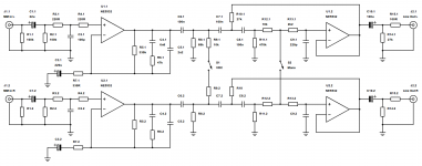
Unfortunately I never got round to building a proper prototype, but here's a much simpler schematic that performs pretty much the same thing without the dynamic loading (although the filters are not as steep) using the ubiquitous and more forgiving (in terms of layout tolerance/stability) 5532.
Unfortunately I never got round to building a proper prototype, but here's a much simpler schematic that performs pretty much the same thing without the dynamic loading (although the filters are not as steep) using the ubiquitous and more forgiving (in terms of layout tolerance/stability) 5532.
Attachments
- Status
- This old topic is closed. If you want to reopen this topic, contact a moderator using the "Report Post" button.
- Home
- Source & Line
- Analogue Source
- Deluxe Phonostage with Vertical Rumble Filter