Konnichiwa,
Well, looking at this it seems very unlike the l'Pacific, about as much as can be, unless we define "J-Fet Phono with passive EQ" as being "l'Pacific". Also, I am not sure I'd call most of the applied design features "enhancements".
Any comments on the nature of T1 & T2?
The schematic is pretty simple.
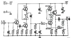
Lets start with the output, it is a J-Fet SRPP with an added Emitter Follower and halve a ton of negative feedback around it. As inverting amplifier it uses the input resistor as part of the RIAA as it becomes the load. Due the rather low open loop gain the summing junction is far from being truely zero ohn and it's impedance will be signal dependent, hence I would say this "enhancement" is pretty daft. While SRPP and Feedback improve aparent linearity, they do not really do so any better than cascoding and using a lower cascode load to bring gain in line.
The RIAA BTW clearly is drawn incorrectly, the 12K1 resistor belongs in series with the 1u Cap. Now the 1uF capacitor will interact with the RIAA turnover frequencies, a better solution is to have the coupling cap after the RIAA, prior to a large value gate leak resistor (1M is usually no issue), which also allows much smaller values while retaining a lower Cutoff. Also, doing so will ensure that the RIAA Capacitors (dielectric) are biased, which helps especially if the RIAA Cap's use sub-ideal dielectrics such as teflon/ptfe, polystyrene or mica (ideal is Vaccum & Air). The RIAA hence strikes me as ill considered at best.
The stage before the RIAA is another SRPP, not much unusual, the output from the upper FET source will give a low drive impedance to the RIAA, however an added Emitter follower may have been a better choice, or perhaps cascoding the J-Fet with a BJT and including the Drain Load as part of the RIAA. The Input buffer is needed due to the large and signal dependent input capacitance of the J-Fet in common source operation. If the J-Fet is cascoded with a BJT the "miller" part of this capacitance is eliminated and as the drain voltage is kept constant the voltage dependance of the input capacity is minimised. So, the input stage all considered is a pretty poor application.
All in all the circuit (after correction) will sort of work, but it shows many signs of a lack of comprehension of basic circuit design issues when designing Phonostages and/or when designing with J-Fets. Maybe the Designer would have benefited from reading Erno Borbelys J-Fet Articles in Audio Electronics?
The buffer is needed if the circuit is used with MM Pickups.
It is comparably smart, considering the rest of the circuit, actually.
Sayonara
peranders said:I have got the swedish edition of Elektor and there is a RIAA amp which uses JFET's. The design is very similar to the Pacific phono amp but it seems that this design has got a few enhancements. Maybe someone can fill in with schematics?
Well, looking at this it seems very unlike the l'Pacific, about as much as can be, unless we define "J-Fet Phono with passive EQ" as being "l'Pacific". Also, I am not sure I'd call most of the applied design features "enhancements".
peranders said:The schematics
Any comments on the nature of T1 & T2?
The schematic is pretty simple.
Lets start with the output, it is a J-Fet SRPP with an added Emitter Follower and halve a ton of negative feedback around it. As inverting amplifier it uses the input resistor as part of the RIAA as it becomes the load. Due the rather low open loop gain the summing junction is far from being truely zero ohn and it's impedance will be signal dependent, hence I would say this "enhancement" is pretty daft. While SRPP and Feedback improve aparent linearity, they do not really do so any better than cascoding and using a lower cascode load to bring gain in line.
The RIAA BTW clearly is drawn incorrectly, the 12K1 resistor belongs in series with the 1u Cap. Now the 1uF capacitor will interact with the RIAA turnover frequencies, a better solution is to have the coupling cap after the RIAA, prior to a large value gate leak resistor (1M is usually no issue), which also allows much smaller values while retaining a lower Cutoff. Also, doing so will ensure that the RIAA Capacitors (dielectric) are biased, which helps especially if the RIAA Cap's use sub-ideal dielectrics such as teflon/ptfe, polystyrene or mica (ideal is Vaccum & Air). The RIAA hence strikes me as ill considered at best.
The stage before the RIAA is another SRPP, not much unusual, the output from the upper FET source will give a low drive impedance to the RIAA, however an added Emitter follower may have been a better choice, or perhaps cascoding the J-Fet with a BJT and including the Drain Load as part of the RIAA. The Input buffer is needed due to the large and signal dependent input capacitance of the J-Fet in common source operation. If the J-Fet is cascoded with a BJT the "miller" part of this capacitance is eliminated and as the drain voltage is kept constant the voltage dependance of the input capacity is minimised. So, the input stage all considered is a pretty poor application.
All in all the circuit (after correction) will sort of work, but it shows many signs of a lack of comprehension of basic circuit design issues when designing Phonostages and/or when designing with J-Fets. Maybe the Designer would have benefited from reading Erno Borbelys J-Fet Articles in Audio Electronics?
tschrama said:The circuit starts of with a buffer.. why? Won't that limmit the dynamic range unnecceserraly (uhhhh how do we spell that?) ..
The buffer is needed if the circuit is used with MM Pickups.
analog_sa said:That buffer stage seems amazingly dumb.
It is comparably smart, considering the rest of the circuit, actually.
Sayonara
- Status
- This old topic is closed. If you want to reopen this topic, contact a moderator using the "Report Post" button.