Boy Frank you arent kidding. I just called ESRC and he said he has seen 3 or so of either in the last 10 years!
So I guess Im back to my original question any suggestions for a 12.6 volt filament tube, that can be used in place of 6dj8 without redesigning the circuit or at least much
So I guess Im back to my original question any suggestions for a 12.6 volt filament tube, that can be used in place of 6dj8 without redesigning the circuit or at least much
You can wire heaters in series, so that two 6.3V heated tubes are used from a 12.6V filament supply. Either AC or DC can work.
If you're using AC heaters, and since 'DJ8 tubes have modest heater current requirements, maybe you can DC-rectify your AC heater supply and regulate down to 6V DC? Then you could use 6DJ8 or one of its equivalents.
--
If you're using AC heaters, and since 'DJ8 tubes have modest heater current requirements, maybe you can DC-rectify your AC heater supply and regulate down to 6V DC? Then you could use 6DJ8 or one of its equivalents.
--
You can also take a 15V DC heater supply, use a current regulator set to 600mA (300mA each for 12AX7 at 6V and 6DJ8) and wire the heaters in series (12V DC total). The tubes' heaters will draw their preferred current, which should stabilize the voltage at the proper place (12V DC, or 6V DC for each series heater). This should work well since both the 12AX7 heater wired for 6V and the 6DJ8 heater draw the same current (300mA or thereabouts).
Just a thought.
Just a thought.
Just finished building one of these with a battery powered 2SK170 stage in front for my AT-F7. No fancy components - just stuff I had in my spares box, but it sounds excellent - much prefer it to the rather shouty and forward presentation of my Trichord Dino. It definitely carries a tune well - some tracks even sound as if they are playing faster. Downsides? initially there seems to be less 'punch' and bass extension that the Trichord. I'm ok with that trade off but I suspect that with some decent components and a proper power supply, this could be improved.
Member
Joined 2009
Paid Member
The sound is fluid in the mid with no harsh elements, it is certainly more forgiving than the Cornet2. Bass and timing is easily the best of the bunch. There is an ease of presentation coupled with a bouncy sound and fluidity to the music that I reckon over time will mean this will be my 1st choice ...
It outperforms phono pres from other galaxies and my friend Jaques Chirac says its the best phono pre he's ever heard bar none.
I have built this phono preamp and I must say it seems a definate step up from the VSPS which I built previously.
Lots of praise - I'd like to know if anybody has moved on to something else or are they still liking their phono from this thread ?
And did anybody compare with the other phono that Thorsten helped improve - the EAR 384 - how do these two compare ?
I'm in the process of building Thorsten's sehematic; It seems to be at my skill level and I have the parts.
I'm laying out the chassis now when I ran into a beginner question that led me down the rabbit hole so to speak. It's specific to this preamp, but general to preamps of this type so if it belongs in another thread let me know.
It concerns the signal ground(s) in a phono pre .. should the left and right sections share a common signal ground or should they be separate running back to a star and ultimately the IEC/earth chassis connection? If left and right were separate, ground left/in and left/out would be connected though I guess.
Also, I'm working through some references on input and output that say ground for left/right input and left/right output should be tied together (but separately). I see it done both ways though.
Lastly, would a lift switch that disconnects the signal ground(s) from everything else be appropriate? At this point I could go either way because I am early in construction. Either way I am constructing in a way that will allow me to stop, test and adjust where necessary.
I am using some of the links referenced here among other for reference but thought I'd ask
My one was a quick build that had to fit in a small case. I just used a copper bus bar attached to input and output sockets for both channels at one end and the chassis at the other. Component assemblies were built up between the valve bases and the bus bar. No issues with hum or noise but star grounding is probably better if you can.
Now using a 417a / 6GK5 phono stage that is star grounded with each stage built into a separate screened box. Something like the circuit here . You can see from the schematic how the stars have been arranged and how left and right sides connect. this arrangement works very well and is silent.
Now using a 417a / 6GK5 phono stage that is star grounded with each stage built into a separate screened box. Something like the circuit here . You can see from the schematic how the stars have been arranged and how left and right sides connect. this arrangement works very well and is silent.
I built this up on a tag board and the only way I could get it quiet was by following the ground scheme on the Toccata. When I did that, the hum went away instantly. With both channels sharing a valve, I tied cartridge input to the input stage star and output to the output stage star. I had a bus bar between stages and tied to the center of that for my power and ground taps.
I'm in the process of building Thorsten's sehematic; It seems to be at my skill level and I have the parts.
I'm laying out the chassis now when I ran into a beginner question that led me down the rabbit hole so to speak. It's specific to this preamp, but general to preamps of this type so if it belongs in another thread let me know.
It concerns the signal ground(s) in a phono pre .. should the left and right sections share a common signal ground or should they be separate running back to a star and ultimately the IEC/earth chassis connection? If left and right were separate, ground left/in and left/out would be connected though I guess.
Also, I'm working through some references on input and output that say ground for left/right input and left/right output should be tied together (but separately). I see it done both ways though.
Lastly, would a lift switch that disconnects the signal ground(s) from everything else be appropriate? At this point I could go either way because I am early in construction. Either way I am constructing in a way that will allow me to stop, test and adjust where necessary.
I am using some of the links referenced here among other for reference but thought I'd ask
I think this here is the clearest and easiest to understand intro to grounding discussion I've found, from diyAudio member MerlinB:
The Valve Wizard
You can download a copy of the PDF too.
--
I built this up on a tag board and the only way I could get it quiet was by following the ground scheme on the Toccata. When I did that, the hum went away instantly. With both channels sharing a valve, I tied cartridge input to the input stage star and output to the output stage star. I had a bus bar between stages and tied to the center of that for my power and ground taps.
That sounds useful. I would not have thought to do that.
That schematic seems to answer my questions plus a few others I didn't askMy one was a quick build that had to fit in a small case. I just used a copper bus bar attached to input and output sockets for both channels at one end and the chassis at the other. Component assemblies were built up between the valve bases and the bus bar. No issues with hum or noise but star grounding is probably better if you can.
Now using a 417a / 6GK5 phono stage that is star grounded with each stage built into a separate screened box. Something like the circuit here . You can see from the schematic how the stars have been arranged and how left and right sides connect. this arrangement works very well and is silent.
. I had to take some time to digest it all. Brilliant work with current regulated filament circuit etc. The writeup and schematic showing local stars for grounding ties the whole thing together.I will probably connect grounds left/right in and left/right out and then use local stars in each channel. I've already decided to make the panel for inputs and outputs removable to allow for work to be done afterwards (space considerations). I could then perhaps do the old 10nf to chassis thing on the inputs or outputs.
I do have a pretty good basic understanding of grounding; my amps to date have been absolutely quiet. But this is my first preamp and really need to keep it quiet. I got hung up on tying the two channels together, bonding left/right inputs and outputs. It seems counterintuitive -- some of those techniques look like loops rather than local grounds. I guess I'm trying to avoid cross-channel loops/hum.
Thanks for setting me straight! Going to hit the books and read some of these downstream posts.
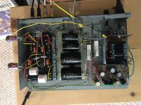
I built Mr. Thorsten's Phono Preamp. It is absolutely silent and sounds wonderful. I have some surface noise from the needle but that's my TT I'm sure. I have nothing to compare it to unfortunately. It is replacing a Chinese hybrid phono pre and I have no long history with high end stuff.
I am very pleased and anxious to get it on the scope. But first some listening.
I'm sharing a picture and schematic. I needed to document the power supply and detail of little stuff.
There were some challenges and errors on my part but all is well now. If anyone has comments or critiques I'd love it.
I am very pleased and anxious to get it on the scope. But first some listening.
I'm sharing a picture and schematic. I needed to document the power supply and detail of little stuff.
There were some challenges and errors on my part but all is well now
. If anyone has comments or critiques I'd love it.Attachments
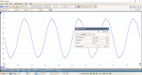
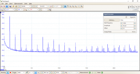
I generated a 1KHz sine wave based on 10 millivolts. Just a signal in and out straight from probes and short test leads. I have no idea how to properly measure a preamp.
Any thoughts? I see a lot of harmonics but I don't have a world of experience under my belt. My voltage is a little low but I still get to 41db if I calculated correctly.
Any thoughts? I see a lot of harmonics but I don't have a world of experience under my belt. My voltage is a little low but I still get to 41db if I calculated correctly.
Attachments
I know this is super old, but I am interested in building this preamp and was looking for this schematic, however the link seems to be so old it doesn't go to the correct threat. A long time ago I know, but thought I would at least ask. Thanks!Konnichiwa,
See post 28 in thishere thread:
http://www.diyaudio.com/forums/showthread.php?postid=338903#post338903
Sayonara
- Home
- Source & Line
- Analogue Source
- DC phono