Konnichiwa,
I prefer Mica types, I will agree that this may be a matter of taste.
I use standard precision metal film, nonmagnetic leads, sadly magnetic endcaps.
No, those where the inserts are PTFE. They tend to be however also those that take covers, often an apropriate choice for low level circuits.
I like really good transformers better than solid state stepup and never got valve based stuff to work quietly enough. I had the original S&B TX-103 (quite expensive) designed to conform with my personal sonic prejudices.
The Phonostage as shown will work well with a TX-103 as MC Stepup and a TX-102 as volume control (without the +6db stepup recommended). Overall gain for MC will be up 68db, usually enough for all but extremely low output (< 0.2mV) MC's....
Looks on one hand a little overkill (a stereo chassis will draw around 30mA only) and at the same time not anywhere near quiet enough in terms of ripple rejection.
I would recommend a simple LM317 type adjustable regulator with a voltage limiting series transistor. This tends to work well enough, the original design was aimed to be used with that. Use a snubbered (Buddah style) solid state bridge made from soft switching diodes with 240V secondary.
The original idea was to use a pair 115V+115V : 9V+9V Transformers back to back, use the 9V+9V with a dual schottky diode for the heater supply and use the second transformers nominal primary as the HT source. Added RC or LC filtering for the raw voltage feeding the HT Stepup transformer is easily implemented.
A simple RCRC Filter after the bridge and an LM317 plus voltage boost transistor give a quiet supply. The RC decoupling per stage makes sure that the Signal current AC loops are closed through the local film capacitors and not the regulator.
I hope this helps to understand what was originally intended.
I don't believe, I know.
The lower the levels the more you get trouble with DA (dielectric absorbtion), especially in areas where the dielectric is not "prebiased", but also where miller capacitance etc. is concerned, also PTFE Sockets tend to have a somewhat dampening effects on microphonics. Clearly all this is beneficial everywhere, but the lower the signals the greater the benefit.
Current production PTFE Sockets cost a mint, old stock military sockets are still quite common however. Once of these days I will actually buy some ceramic Octal & UX-4 sockets, salvage the contacts from them and apply them to homemade sockets in solid PTFE stock or maybe C37 infused wood (loads of air in wood - surprisingly good dielectric once suitably dry and sealed)....
Sayonara
GAK said:- silver/mica or polysterene?
I prefer Mica types, I will agree that this may be a matter of taste.
GAK said:Any suggestion for the signal resistors (215K , 48K7 , 100R) ?
I use standard precision metal film, nonmagnetic leads, sadly magnetic endcaps.
GAK said:What is PTFE valve sockets?Those with the can that covers the valve?
No, those where the inserts are PTFE. They tend to be however also those that take covers, often an apropriate choice for low level circuits.
GAK said:In the future I'm planning to use an MC cartridge.Step-up with xformers or active?
I like really good transformers better than solid state stepup and never got valve based stuff to work quietly enough. I had the original S&B TX-103 (quite expensive) designed to conform with my personal sonic prejudices.
The Phonostage as shown will work well with a TX-103 as MC Stepup and a TX-102 as volume control (without the +6db stepup recommended). Overall gain for MC will be up 68db, usually enough for all but extremely low output (< 0.2mV) MC's....
GAK said:Any comments-suggestions for the following PSU?
Looks on one hand a little overkill (a stereo chassis will draw around 30mA only) and at the same time not anywhere near quiet enough in terms of ripple rejection.
I would recommend a simple LM317 type adjustable regulator with a voltage limiting series transistor. This tends to work well enough, the original design was aimed to be used with that. Use a snubbered (Buddah style) solid state bridge made from soft switching diodes with 240V secondary.
The original idea was to use a pair 115V+115V : 9V+9V Transformers back to back, use the 9V+9V with a dual schottky diode for the heater supply and use the second transformers nominal primary as the HT source. Added RC or LC filtering for the raw voltage feeding the HT Stepup transformer is easily implemented.
A simple RCRC Filter after the bridge and an LM317 plus voltage boost transistor give a quiet supply. The RC decoupling per stage makes sure that the Signal current AC loops are closed through the local film capacitors and not the regulator.
I hope this helps to understand what was originally intended.
GAK said:Teflon?
Kuei: Do you believe that PTFE sockets are better for phonostage?
I don't believe, I know.
GAK said:What about other projects like amps , preamps?
The lower the levels the more you get trouble with DA (dielectric absorbtion), especially in areas where the dielectric is not "prebiased", but also where miller capacitance etc. is concerned, also PTFE Sockets tend to have a somewhat dampening effects on microphonics. Clearly all this is beneficial everywhere, but the lower the signals the greater the benefit.
Current production PTFE Sockets cost a mint, old stock military sockets are still quite common however. Once of these days I will actually buy some ceramic Octal & UX-4 sockets, salvage the contacts from them and apply them to homemade sockets in solid PTFE stock or maybe C37 infused wood (loads of air in wood - surprisingly good dielectric once suitably dry and sealed)....
Sayonara
Kuei
Have you actually compared a 317 based regulator to a tube-series regulator in a phono stage?
And you really preferred the 317?!?!?
What about giving up the regulator completely and using multiple LC filters. With maybe a gas tube at the end to keep the voltage constant. Low noise and strong bass are not the most essential sound priorities for everyone.
Konnichiwa,
Yes.
Nope, i found very little difference. The LM317 solution is simpler, cheaper and actually quieter.
This is what I am doing with my current "in system" phonostage. But as uncompromising an approach as I took there may not be for everyone. The point with the ECC83/ECC88 Phonostage is to provide a good basic quality phonos that is easy and fairly inexpensive to realise (it was originally aimed at a commercial application).
Anyone who wants a truely outstanding phonostage has to work harder than that, but to many it will likely serve well. Think of it as the "Valve - El Cheapo" to give you an idea where it fits in in the whole scheme of things. It is not "the latest & greatest", far from it. But it is "pretty good".
Constant voltage is not really an issue. I prefer a good quality cap to a gas regulator (tried). Please note that the LM317 is PRE-Regulator followed by an RC filter. For those paranoid enough - you can add another 1k/22uF section to the output stage and split the input stages 180k Resistor into 2pcs of 91k and use a pair of 10uF Cap's.
With the original circuit, the LM317 regulator output (AC - be it noise or reaction to the AC current demand of the output stage) is suppressed by around 23db @ 100Hz and 40db @ 1KHz. Doubling the RC circuits doubles that attenuation.
Also note that the RC circuit drastically reduces the current modulation on the LM317 in the first place. At 20Hz only 1/4 of the current flowing in the output stage feeds back as modulation of the LM317 output, at 100Hz it is only 0.072 times the current in the output stage.
Thus the single RC circuit after the regulator insulates the Signal circuit from any signal interactions with the regulator by around 45db @ 100Hz and much more than that above 100Hz, compared to feeding the circuit DIRECTLY from the regulator. So the solid state regulator only becomes audible at very low frequencies.
If you feel 45db down @ 100Hz is not enough, doubling the RC circuits up gets you > 90db reduction of signal related "nasties" from the "bad & evil" solid state regulator at 100Hz.... As always, it is less what you but how....
They are not priorites as such for me either. Low noise of course is not a priority, it is essential, as is in general a reasonably good sound.
Sayonara
analog_sa said:Have you actually compared a 317 based regulator to a tube-series regulator in a phono stage?
Yes.
analog_sa said:And you really preferred the 317?!?!?
Nope, i found very little difference. The LM317 solution is simpler, cheaper and actually quieter.
analog_sa said:What about giving up the regulator completely and using multiple LC filters.
This is what I am doing with my current "in system" phonostage. But as uncompromising an approach as I took there may not be for everyone. The point with the ECC83/ECC88 Phonostage is to provide a good basic quality phonos that is easy and fairly inexpensive to realise (it was originally aimed at a commercial application).
Anyone who wants a truely outstanding phonostage has to work harder than that, but to many it will likely serve well. Think of it as the "Valve - El Cheapo" to give you an idea where it fits in in the whole scheme of things. It is not "the latest & greatest", far from it. But it is "pretty good".
analog_sa said:With maybe a gas tube at the end to keep the voltage constant.
Constant voltage is not really an issue. I prefer a good quality cap to a gas regulator (tried). Please note that the LM317 is PRE-Regulator followed by an RC filter. For those paranoid enough - you can add another 1k/22uF section to the output stage and split the input stages 180k Resistor into 2pcs of 91k and use a pair of 10uF Cap's.
With the original circuit, the LM317 regulator output (AC - be it noise or reaction to the AC current demand of the output stage) is suppressed by around 23db @ 100Hz and 40db @ 1KHz. Doubling the RC circuits doubles that attenuation.
Also note that the RC circuit drastically reduces the current modulation on the LM317 in the first place. At 20Hz only 1/4 of the current flowing in the output stage feeds back as modulation of the LM317 output, at 100Hz it is only 0.072 times the current in the output stage.
Thus the single RC circuit after the regulator insulates the Signal circuit from any signal interactions with the regulator by around 45db @ 100Hz and much more than that above 100Hz, compared to feeding the circuit DIRECTLY from the regulator. So the solid state regulator only becomes audible at very low frequencies.
If you feel 45db down @ 100Hz is not enough, doubling the RC circuits up gets you > 90db reduction of signal related "nasties" from the "bad & evil" solid state regulator at 100Hz.... As always, it is less what you but how....
analog_sa said:Low noise and strong bass are not the most essential sound priorities for everyone.
They are not priorites as such for me either. Low noise of course is not a priority, it is essential, as is in general a reasonably good sound.
Sayonara
Keui
- Could you please explain me the role of the 48K7 resistor ?
- To add the 3.18 usec I need to add 3k18 in series to 1n, right?
- Any comments about the sonics compared to Claret and Pacific copies of yours? (I have tried both.. I play the pacific for now)
- Are you refering to Morgan Jones 317 style regulator ?
- What about your Mosfet regulator ?
Analog SA
- With extended low end (soft suspension driver) speakers it is impossible for me to fight low frequency oscilations with all passive PSU.
For the last 6 months I tried nearly everything SS rectifiers, dampers, GZ34, EZ81, Hybrid, RC filtering, LC filtering, mixed .... nada. It seems to me that an all passive PSU is a highly tuned sytem that needs proper measuring facilities that the average DIYer, like me, doesn't have (at the moment...).
I tried Morgan Jones regulator and I have to say that I like it very much. No oscilations or other nasties and sufficiently transparent to play with rectifiers and capacitors and get more than strong bass and low noise..
The above powers a 6BX7 grounded cathode line stage that I use and tweak for the last 3 years .
- With extended low end (soft suspension driver) speakers it is impossible for me to fight low frequency oscilations with all passive PSU.
I can't for the life of me see what the soft suspension has to do with anything. You may be experiencing a complex phenomena where ground loops interact with the PS over several stages to produce oscillations. The fact that a low impedance regulator stops the oscillations seems to indicate poor grounding. Of course i may be wrong
") I don't experience such issues as i firmly believe in star topologies in both the grounds and B+ loops and as good as possible separation between separate stages PSs. Of course the best solution for sonics is a completely separate PS for each stage anyway.
I don't experience such issues as i firmly believe in star topologies in both the grounds and B+ loops and as good as possible separation between separate stages PSs. Of course the best solution for sonics is a completely separate PS for each stage anyway.Hi,
The only part that may require some amount of fine tuning is the relation between the filtercaps and the choke(s) in an LC filter.
You'd be surprised how often I see resonance tanks passed on as power supplies....
You can get a pretty accurate idea by using a free proggie like PSUD II.
Of course no amount of sw simulation is going to tell you where the ground loop is...
With all the LF junk passing through I'm surprised the woofers have survived this kind of torture test...
Amen.
Cheers,
It seems to me that an all passive PSU is a highly tuned sytem that needs proper measuring facilities that the average DIYer, like me, doesn't have (at the moment...).
The only part that may require some amount of fine tuning is the relation between the filtercaps and the choke(s) in an LC filter.
You'd be surprised how often I see resonance tanks passed on as power supplies....
You can get a pretty accurate idea by using a free proggie like PSUD II.
Of course no amount of sw simulation is going to tell you where the ground loop is...
With all the LF junk passing through I'm surprised the woofers have survived this kind of torture test...
Of course the best solution for sonics is a completely separate PS for each stage anyway.
Amen.
Cheers,
Konnichiwa,
RIAA EQ, what else?
The type of RIAA EQ shown offers the combined advantages of "single stage" and "2-stage" passive RIAA EQ networks.
Yes. However if you do that consider implementaing fully switchable EQ, including 3uS, 6uS and 10uS added HF shelf and the varied LF and HF turnover points at 100uS and 75uS as well as LF rolloff points at 3180uS, 1590uS and 1270uS. Try compensating the excess gain from the LF rolloff compensation to make switchable comparisons more meaningful. If you really want an accurate EQ you need to try a lot harder than just RIAA @ +/-0.1db, whcih is easily achieved.
The Claret MUST be taken as full Preamplifier and in the right system context. You CANNOT compare it to a standalone phonestage in any meaningful way. The Claret is notably off what we consider "neutral", yet in a muciaclly meaningful way. It makes virtually everything sound "good", a neat trick if you can pull it off.
Pacific and "El Cheapo" are more neutral, "El Cheapo" perhaps to a fault. This Valve Phonostage also falls more into the "neutral" camp, but tends to share some of the Pacifics attributes, except it sounds more "tube" like, in the positive meaning (e.g. not meaning syrupy colorations that oversugar everything). I prefer this basic Phono to the EAR, which i think is better than the Pacific, given sufficient care in the implementation (especially PSU).
Not sure what that is. I know Morgan personally but never felt the need to read his book (or most others for that).
It's not a regulator (1) and it seems to be somewhat testy. I have build quite a few of these and never once did I have one oscillating on me, blowing up etc... It does often seem to happen to others though, hence I prefer not to recommend it. Again, the sonic differences are small after you intersperse a sufficiently large timeconstant RC Circuit after the regulator. So a recommendation based on "get it working easily....".
Sayonara
Marinos said:- Could you please explain me the role of the 48K7 resistor ?
RIAA EQ, what else?
The type of RIAA EQ shown offers the combined advantages of "single stage" and "2-stage" passive RIAA EQ networks.
Marinos said:- To add the 3.18 usec I need to add 3k18 in series to 1n, right?
Yes. However if you do that consider implementaing fully switchable EQ, including 3uS, 6uS and 10uS added HF shelf and the varied LF and HF turnover points at 100uS and 75uS as well as LF rolloff points at 3180uS, 1590uS and 1270uS. Try compensating the excess gain from the LF rolloff compensation to make switchable comparisons more meaningful. If you really want an accurate EQ you need to try a lot harder than just RIAA @ +/-0.1db, whcih is easily achieved.
Marinos said:- Any comments about the sonics compared to Claret and Pacific copies of yours? (I have tried both.. I play the pacific for now)
The Claret MUST be taken as full Preamplifier and in the right system context. You CANNOT compare it to a standalone phonestage in any meaningful way. The Claret is notably off what we consider "neutral", yet in a muciaclly meaningful way. It makes virtually everything sound "good", a neat trick if you can pull it off.
Pacific and "El Cheapo" are more neutral, "El Cheapo" perhaps to a fault. This Valve Phonostage also falls more into the "neutral" camp, but tends to share some of the Pacifics attributes, except it sounds more "tube" like, in the positive meaning (e.g. not meaning syrupy colorations that oversugar everything). I prefer this basic Phono to the EAR, which i think is better than the Pacific, given sufficient care in the implementation (especially PSU).
Marinos said:- Are you refering to Morgan Jones 317 style regulator ?
Not sure what that is. I know Morgan personally but never felt the need to read his book (or most others for that).
Marinos said:- What about your Mosfet regulator ?
It's not a regulator (1) and it seems to be somewhat testy. I have build quite a few of these and never once did I have one oscillating on me, blowing up etc... It does often seem to happen to others though, hence I prefer not to recommend it. Again, the sonic differences are small after you intersperse a sufficiently large timeconstant RC Circuit after the regulator. So a recommendation based on "get it working easily....".
Sayonara
You can get a pretty accurate idea by using a free proggie like PSUD II.
No evidence of the problem with PSUD II.
A repeatable wrong practice in grounding ? most possible ...
With all the LF junk passing through I'm surprised the woofers have survived this kind of torture test..
This is where the "soft suspension" comes in.... I'm kidding.
I have no other way but "seeing" the oscilation.. Of course I power down immediately.
Not sure what that is.
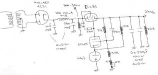
This is the schematic
Attachments
The conclusion is to use four separate PSUs?One for each stage??
Too extreme for now.Let's make it simpler and if it's everything ok I'll try it in the future.
Why not to use one power xformer,rectification,p-filter and then split in two separate regulated supplies (tube or SS).One for each channel with an RC filter after each section.This for the PSU chassis.
For the circuit chassis ,an other RC filter for each channel and then Kuei's circuit as is in the schem.
Kuei:
- How much expensive is the S&B TX-103?
- What about Sowther and Lundahl?
- You have right that it's an overkill to go with the PSU I was thinking to use.
But I'd like to try tube based voltage regulators.I don't have in mind something better.
Who can help on this?
Frank: It's also an overkill to use your PSU with EL86,right?Or not?
Hi,
Marinos,
You'll stop laughing when the coil gets stuck in the former...
Anyway, it sounds ( pun not intended ) as if you have DC on the output, either the DC constant of you coupling caps is at such low frequency that it somehow passes low frequency instability or you could have a faulty DC blocking cap somewhere.
Gak,
I wouldn't consider it overkill for a phono preamp...
After the series reg I'd just put some reservoir caps, no further filtering should be required.
Well, compared to the circuit with the 6AS7G, no, I wouldn't consider it overkill.
If you need a regulated 250VDC B+ a ECL805/85 and a 85A2 would do per stage ( depending on current requirements perhaps one per channel may do ) and should be better and maybe also cheaper than just one with a 6AS7G which is only needed if the reg needs to work for (a) stage(s) drawing much more current.
If the ECL82 is considerably cheaper than the ECL85/805 than that would be fine too...
I should have a schematic for one of those in my drawer somewhere...
To my mind there's little point in adding a series or shunt reg and than share amongst stages/channels in a preamp.
The least you should do is have one per channel to avoid interchannel IMD.
Cheers,
Marinos,
This is where the "soft suspension" comes in.... I'm kidding.
You'll stop laughing when the coil gets stuck in the former...
Anyway, it sounds ( pun not intended ) as if you have DC on the output, either the DC constant of you coupling caps is at such low frequency that it somehow passes low frequency instability or you could have a faulty DC blocking cap somewhere.
Gak,
The conclusion is to use four separate PSUs?One for each stage??
I wouldn't consider it overkill for a phono preamp...
Why not to use one power xformer,rectification,p-filter and then split in two separate regulated supplies (tube or SS).One for each channel with an RC filter after each section.This for the PSU chassis.
After the series reg I'd just put some reservoir caps, no further filtering should be required.
Frank: It's also an overkill to use your PSU with EL86,right?Or not?
Well, compared to the circuit with the 6AS7G, no, I wouldn't consider it overkill.
If you need a regulated 250VDC B+ a ECL805/85 and a 85A2 would do per stage ( depending on current requirements perhaps one per channel may do ) and should be better and maybe also cheaper than just one with a 6AS7G which is only needed if the reg needs to work for (a) stage(s) drawing much more current.
If the ECL82 is considerably cheaper than the ECL85/805 than that would be fine too...
I should have a schematic for one of those in my drawer somewhere...
To my mind there's little point in adding a series or shunt reg and than share amongst stages/channels in a preamp.
The least you should do is have one per channel to avoid interchannel IMD.
Cheers,
What about Sowther and Lundahl?
I have some experience with Lundahl LL9206 and while not perfect it seems amazing value for the money. I also have little doubt that the TX103 is much better, especially in the bass, as it should be at 4 times the price.
Konnichiwa,
Nope, one regulated and LOW NOISE supply providing 250V with a little over 30mA current Capacity is fine. An ECL82 on it's own should manage fine, if you want valves. Just keep the ripple low.
The seperate RC decoupling circuits to each stage move the sound critical bit's into the decoupling Cap's and strongly reduce the sonic effect of the PSU.
Sure, as said, a decent, low noise regulated supply will be fine.
Check with the distributors (Bent Audio & DIY HiFisupply). If you want an idea what others think of it, look here:
http://www.high-endaudio.com/RC-Step-ups.html#ClB
http://www.hagtech.com/trumpet.html#stepup
http://www.positive-feedback.com/Issue11/hagerman.htm
The Sowters I tried had me persuing J-Fet/Valve cascodes instead. I had the original 103 designed for myself to solve what I percieved to be the fundamental issues with all the MC Stepup's I had tried up to that point. It seems others like it too.
Sayonara
GAK said:The conclusion is to use four separate PSUs?One for each stage??
Nope, one regulated and LOW NOISE supply providing 250V with a little over 30mA current Capacity is fine. An ECL82 on it's own should manage fine, if you want valves. Just keep the ripple low.
The seperate RC decoupling circuits to each stage move the sound critical bit's into the decoupling Cap's and strongly reduce the sonic effect of the PSU.
GAK said:Why not to use one power xformer,rectification,p-filter and then split in two separate regulated supplies (tube or SS).One for each channel with an RC filter after each section.This for the PSU chassis.
Sure, as said, a decent, low noise regulated supply will be fine.
GAK said:- How much expensive is the S&B TX-103?
Check with the distributors (Bent Audio & DIY HiFisupply). If you want an idea what others think of it, look here:
http://www.high-endaudio.com/RC-Step-ups.html#ClB
http://www.hagtech.com/trumpet.html#stepup
http://www.positive-feedback.com/Issue11/hagerman.htm
GAK said:- What about Sowther and Lundahl?
The Sowters I tried had me persuing J-Fet/Valve cascodes instead. I had the original 103 designed for myself to solve what I percieved to be the fundamental issues with all the MC Stepup's I had tried up to that point. It seems others like it too.
Sayonara
Frank
Can you post any schem with ECL82 or 85?
Ok I'll put only caps.
You mean one reg per channel or a whole PSU per channel?
Kuei
So there's no any problem if PSU is tube based or SS.
Wouldn't be better to use larger cap's over there?I have some MKP at 33uF and 47uF at 400V.
Can you post any schem with ECL82 or 85?
After the series reg I'd just put some reservoir caps, no further filtering should be required.
Ok I'll put only caps.
The least you should do is have one per channel to avoid interchannel IMD.
You mean one reg per channel or a whole PSU per channel?
Kuei
The seperate RC decoupling circuits to each stage move the sound critical bit's into the decoupling Cap's and strongly reduce the sonic effect of the PSU.
So there's no any problem if PSU is tube based or SS.
Wouldn't be better to use larger cap's over there?I have some MKP at 33uF and 47uF at 400V.
Konnichiwa,
Then the regulator will dominate the sound due to it's transient behaviour. I find most regulators by far too audible (in a negative sense of the word) to place them into signal current loops.
If you retain the RC decoupling as drawn in my schematic one regulator for both channels suffices. Do not delete these RC circuits unless you are very experienced in wringing good sound from circuits with loads of loop feedback and invariably poor transient response (regulator).
It may prove difficult to make valvee regulated supplies sufficiently quiet, other than that, no issue.
Why? Because a lot does a lot of good? Like a lot of paint in one coat, instead of many thin coats and like a ton of glue instead of clean, flat surfaces and only the slightest bit of glue?
Remember, always use the smallest value capacitor you can get away with, the smaller the value the smaller the physical size and the less usually the various evils plaguing them. Leave th 10uF Cap in the first stage alone.
If you must (like having suitable cap's lying about) use larger values place them in the anode circuit of the ECC88, up to 100uF make sense, though a pair of 1k Resistors and of 22uF capacitors will be much more effective.
I would not recommend this phono as "cost no object" project. It's design was emphatically "high cost IS an object".... My "cost no object" design is a notably better but tends to push the parts cost well past the $ 1,000 line. If cost is really no object build that. Otherwise place your "parts money" wisey, where it counts sonically and use the right parts too (quality over quantity), basically the polar oppsite approach of "cost no object"....
Sayonara
GAK said:Ok I'll put only caps.
Then the regulator will dominate the sound due to it's transient behaviour. I find most regulators by far too audible (in a negative sense of the word) to place them into signal current loops.
GAK said:You mean one reg per channel or a whole PSU per channel?
If you retain the RC decoupling as drawn in my schematic one regulator for both channels suffices. Do not delete these RC circuits unless you are very experienced in wringing good sound from circuits with loads of loop feedback and invariably poor transient response (regulator).
GAK said:So there's no any problem if PSU is tube based or SS.
It may prove difficult to make valvee regulated supplies sufficiently quiet, other than that, no issue.
GAK said:Wouldn't be better to use larger cap's over there?
Why? Because a lot does a lot of good? Like a lot of paint in one coat, instead of many thin coats and like a ton of glue instead of clean, flat surfaces and only the slightest bit of glue?
Remember, always use the smallest value capacitor you can get away with, the smaller the value the smaller the physical size and the less usually the various evils plaguing them. Leave th 10uF Cap in the first stage alone.
If you must (like having suitable cap's lying about) use larger values place them in the anode circuit of the ECC88, up to 100uF make sense, though a pair of 1k Resistors and of 22uF capacitors will be much more effective.
I would not recommend this phono as "cost no object" project. It's design was emphatically "high cost IS an object".... My "cost no object" design is a notably better but tends to push the parts cost well past the $ 1,000 line. If cost is really no object build that. Otherwise place your "parts money" wisey, where it counts sonically and use the right parts too (quality over quantity), basically the polar oppsite approach of "cost no object"....
Sayonara
Hi,
The regulator as presented here serves a dual purpose ; it isolate the circuit from the mains to a great extend and it serves as a trickle charger for the reservoir caps behind it.
It has very low ripple and only regulates in the sense that the output voltage is kept constant which in this application is a breeze from the regulators' POV as current draw is constant most of the time: class A remember?
You can replace the Black Gate caps with cheaper caps, untill the budget allows for an upgrade, to either BG or good filmcaps, PIO or the ASC variant.
In order for the regulator to work properly you need to make sure that you have at least 50V more at the input compare to your target voltage. So if you want to have a well regulated 250VDC supply, you'll need at least 300VDC at the input.
More won't hurt but keep an eye on the heater to cathode insulation voltages of the pass device(s).
Cheers,
P.S. The regs using the ECL82 are still on the drawing board.
P.P.S. Keep in mind that you can't draw more current from the reg than the pass device can deliver.
EDIT: I just spotted the 30H 40mA choke in the PS. You can safely lower the Henry value and up the current spec if you need more current from the reg.
It was originally designed to supply a single stage, single channel.
Can you post any schem with ECL82 or 85?
The regulator as presented here serves a dual purpose ; it isolate the circuit from the mains to a great extend and it serves as a trickle charger for the reservoir caps behind it.
It has very low ripple and only regulates in the sense that the output voltage is kept constant which in this application is a breeze from the regulators' POV as current draw is constant most of the time: class A remember?
You can replace the Black Gate caps with cheaper caps, untill the budget allows for an upgrade, to either BG or good filmcaps, PIO or the ASC variant.
In order for the regulator to work properly you need to make sure that you have at least 50V more at the input compare to your target voltage. So if you want to have a well regulated 250VDC supply, you'll need at least 300VDC at the input.
More won't hurt but keep an eye on the heater to cathode insulation voltages of the pass device(s).
Cheers,
P.S. The regs using the ECL82 are still on the drawing board.
P.P.S. Keep in mind that you can't draw more current from the reg than the pass device can deliver.
EDIT: I just spotted the 30H 40mA choke in the PS. You can safely lower the Henry value and up the current spec if you need more current from the reg.
It was originally designed to supply a single stage, single channel.
Attachments
Frank
Thanks for the schem.
I'm planning to use tube rectifier.I have done some changes to the schem.Any comments?
Some more questions
- The reservoir caps after the regulator is better to put them at the PSU chassis or at the circuit chassis?Or to leave them at the PSU chassis and put some other at the circuit chassis?
- I have some PCL86.I can't use them at the place of ECL85 ,right?
- what kind of cap to use at the place of 330n//91K?
- Vkf of ECL85 = 200V.I think I'll have a problem with 250V at the cathode of pentode.
Kuei
- I can't find silver mica bigger than 100V.Any source in EU?
- 2u2:Audyn KP-SN or MKP Hovland?Or sth else?
Thanks for the schem.
I'm planning to use tube rectifier.I have done some changes to the schem.Any comments?
Some more questions
- The reservoir caps after the regulator is better to put them at the PSU chassis or at the circuit chassis?Or to leave them at the PSU chassis and put some other at the circuit chassis?
- I have some PCL86.I can't use them at the place of ECL85 ,right?
- what kind of cap to use at the place of 330n//91K?
- Vkf of ECL85 = 200V.I think I'll have a problem with 250V at the cathode of pentode.
Kuei
I won't do any changes at your schem.I'll leave it as it is.If you retain the RC decoupling as drawn in my schematic one regulator for both channels suffices. Do not delete these RC circuits unless you are very experienced in wringing good sound from circuits with loads of loop feedback and invariably poor transient response (regulator).
- I can't find silver mica bigger than 100V.Any source in EU?
- 2u2:Audyn KP-SN or MKP Hovland?Or sth else?
Konnichiwa,
I'm not frank, BUT, your input LC filter has very low levels of capacitance and inductance, meaning comparably little filtering.
Combine that with the regulator circuit shown (which fails in several areas to realise the maximally possible PSRR), which will have a lot worse ripple rejection than a LM317 you may very well find that the Circuit has too much noise.
To put this simple, the Output Stage of the circuit of my suggested Phonostage (which dominates the PSRR of the Circuit) is around is around 40db. If we assume a 2.5mV Phono cartridge and thus 250mV output from the Phonostage we would like a S/N ratio for the 100Hz PSU component AT LEAST 80db (1:10000) below this. In other words, the supply noise at 100Hz needs to be 40db below the expected signal level as the circuit with it's RC filter already rejects the PSU Noise by 40db.
In plain english, the noise applied to the Phonostage needs yto be 40db below 250mV or no more than 2.5mV. A typhical Valve based regulator does not display all that much 100Hz noise rejection, simply because it tends to have a rather low open loop gain.
The Series Pass Valve is a simple cathode follower. It's grid will receive an AC voltage that is a fraction of the noise on the valves anode (unless the gridvoltage is additionally filtered) determined by the value of the Anode resistor of the differential Amp valve and it's anode resistance. The cathode will attempt to follow this voltage but will experience additional pertubations due to the limited transconductance of the Valve. Combine that with a fairly high ripple pre-regulator the result may simply not be good enough.
I would move one of the 220uF cap's to the position after the choke (or both) and limit the capacitive load after the reggulator to what is needed for stability (usually 10 - 20uF).
You could even dump the Regulator and choke and use multiple RC circuits (Shindo Style), it sounds good and is very cost effective. Simply use a chain of 5 1k resistors and 5 100uF Electrolytic Cap's and make sure your raw DC after rectification and Reservoir Cap is around 400V. The 5 X 1k/100u Filter chain after a 10uF reservoir cap will produces a very low ripple DC (< 1uV 100Hz noise) quite cheaply and effectively.
If you retain the RC decoupling circuits shown in my schematic, you can all the stuff on the PSU chassis, also quality will be a lot less critical.
I buy 500V rated ACL made silver mica cap's from RS Copmonents UK (www.rswww.com).
My choice would Audyn/Mundorf/Angela KP-SN (they are all very similar). I'm not much of fan of the Hovelands or Jensen PIO'. You can always experiemnt later if you want a leaner, more clinical or warmer more cuddly sound.
Sayonara
GAK said:I'm planning to use tube rectifier.I have done some changes to the schem.Any comments?
I'm not frank, BUT, your input LC filter has very low levels of capacitance and inductance, meaning comparably little filtering.
Combine that with the regulator circuit shown (which fails in several areas to realise the maximally possible PSRR), which will have a lot worse ripple rejection than a LM317 you may very well find that the Circuit has too much noise.
To put this simple, the Output Stage of the circuit of my suggested Phonostage (which dominates the PSRR of the Circuit) is around is around 40db. If we assume a 2.5mV Phono cartridge and thus 250mV output from the Phonostage we would like a S/N ratio for the 100Hz PSU component AT LEAST 80db (1:10000) below this. In other words, the supply noise at 100Hz needs to be 40db below the expected signal level as the circuit with it's RC filter already rejects the PSU Noise by 40db.
In plain english, the noise applied to the Phonostage needs yto be 40db below 250mV or no more than 2.5mV. A typhical Valve based regulator does not display all that much 100Hz noise rejection, simply because it tends to have a rather low open loop gain.
The Series Pass Valve is a simple cathode follower. It's grid will receive an AC voltage that is a fraction of the noise on the valves anode (unless the gridvoltage is additionally filtered) determined by the value of the Anode resistor of the differential Amp valve and it's anode resistance. The cathode will attempt to follow this voltage but will experience additional pertubations due to the limited transconductance of the Valve. Combine that with a fairly high ripple pre-regulator the result may simply not be good enough.
I would move one of the 220uF cap's to the position after the choke (or both) and limit the capacitive load after the reggulator to what is needed for stability (usually 10 - 20uF).
You could even dump the Regulator and choke and use multiple RC circuits (Shindo Style), it sounds good and is very cost effective. Simply use a chain of 5 1k resistors and 5 100uF Electrolytic Cap's and make sure your raw DC after rectification and Reservoir Cap is around 400V. The 5 X 1k/100u Filter chain after a 10uF reservoir cap will produces a very low ripple DC (< 1uV 100Hz noise) quite cheaply and effectively.
GAK said:- The reservoir caps after the regulator is better to put them at the PSU chassis or at the circuit chassis?
If you retain the RC decoupling circuits shown in my schematic, you can all the stuff on the PSU chassis, also quality will be a lot less critical.
GAK said:- I can't find silver mica bigger than 100V.Any source in EU?
I buy 500V rated ACL made silver mica cap's from RS Copmonents UK (www.rswww.com).
GAK said:2u2:Audyn KP-SN or MKP Hovland?Or sth else?
My choice would Audyn/Mundorf/Angela KP-SN (they are all very similar). I'm not much of fan of the Hovelands or Jensen PIO'. You can always experiemnt later if you want a leaner, more clinical or warmer more cuddly sound.
Sayonara
Hi,
GAK,
IMO the use of a tube rectifier is not going to bring any sonic or other benefit in this case.
You won't hear the difference, I tried this with this circuit several times and never heard anything in favour of the valve rectifier.
If you want to at all cost than so be it but as TL has pointed out you'll need some extra filtering as the rectifier is limited in the cap it can have straight in front of its output.
If it's the slowstart you're looking for, the regulator provides this plus it isolates the PS nicely from the mains, keeps B+ rocksteady and if you use one per stage IMD will be a thing of the past.
All in all extra expenses that can and are avoided by the BY133 Shottky rectifier bridge.
The regulator will reject alot of ripple but it is limited by its transconductance.
Regarding the 0.330µF cap, you can use an Audyn MKP here too, they're relatively cheap and sound fine.
The regulator as shown has served in a phono stage since 1985 and with a cascaded triode phonostage measured noise is -70dB for phono and -90 dB for line level.
Input sensitivity is 2.25mV into 51K (TL is not alone here) with 100pF in //.
You can put the caps behind the reg in the preamp chassis if you like but I'd add some more MKP caps locally close to the circuit proper.
No, not if you build it as drawn.
Re: PCL86, no, not without a complete redesign...Besides, you can make a nice little amp with those if you have a few of them.
If you need a more sophisticated regulator just let me know, it adds an extra tube and uses a cascode stage as an error amp.
A last remark, I doubt there's any benefit in using MKP caps in front of the reg so quite a few $$ can be saved there.
Cheers,
GAK,
IMO the use of a tube rectifier is not going to bring any sonic or other benefit in this case.
You won't hear the difference, I tried this with this circuit several times and never heard anything in favour of the valve rectifier.
If you want to at all cost than so be it but as TL has pointed out you'll need some extra filtering as the rectifier is limited in the cap it can have straight in front of its output.
If it's the slowstart you're looking for, the regulator provides this plus it isolates the PS nicely from the mains, keeps B+ rocksteady and if you use one per stage IMD will be a thing of the past.
All in all extra expenses that can and are avoided by the BY133 Shottky rectifier bridge.
The regulator will reject alot of ripple but it is limited by its transconductance.
Regarding the 0.330µF cap, you can use an Audyn MKP here too, they're relatively cheap and sound fine.
The regulator as shown has served in a phono stage since 1985 and with a cascaded triode phonostage measured noise is -70dB for phono and -90 dB for line level.
Input sensitivity is 2.25mV into 51K (TL is not alone here) with 100pF in //.
You can put the caps behind the reg in the preamp chassis if you like but I'd add some more MKP caps locally close to the circuit proper.
- Vkf of ECL85 = 200V.I think I'll have a problem with 250V at the cathode of pentode.
No, not if you build it as drawn.
Re: PCL86, no, not without a complete redesign...Besides, you can make a nice little amp with those if you have a few of them.
If you need a more sophisticated regulator just let me know, it adds an extra tube and uses a cascode stage as an error amp.
A last remark, I doubt there's any benefit in using MKP caps in front of the reg so quite a few $$ can be saved there.
Cheers,
You had me!
I think I'll build Kuei's circuit as it is and then I'll try different PSUs.
Then I'll have my own opinion.
It's very funny that everyone has sth different to say.
Frank
If it's easy I'd like to see the more sophisticated regulator.
Kuei
The S&B are too expansive but I think they're worth the money.
In the future I'll try them.Especially the 600R riaa eq.
Can you suggest me sth not so expensive for MC step up?
me!I think I'll build Kuei's circuit as it is and then I'll try different PSUs.
Then I'll have my own opinion.
It's very funny that everyone has sth different to say.
Frank
If it's easy I'd like to see the more sophisticated regulator.
If the nominal is 50K why not to use a 50K resistor?Input sensitivity is 2.25mV into 51K (TL is not alone here) with 100pF in //.
Kuei
The S&B are too expansive but I think they're worth the money.
In the future I'll try them.Especially the 600R riaa eq.
Can you suggest me sth not so expensive for MC step up?
Can you exlain me why the raw DC after rectification and cap must be around 400V?Isn't it too much?You could even dump the Regulator and choke and use multiple RC circuits (Shindo Style), it sounds good and is very cost effective. Simply use a chain of 5 1k resistors and 5 100uF Electrolytic Cap's and make sure your raw DC after rectification and Reservoir Cap is around 400V. The 5 X 1k/100u Filter chain after a 10uF reservoir cap will produces a very low ripple DC (< 1uV 100Hz noise) quite cheaply and effectively.
- Home
- Source & Line
- Analogue Source
- DC phono