I mention it here because it illustrates the advantages to forcing uncorrelated noise sources into common mode. A majority of the noise voltage from uncorrelated current noise develops in common mode (as well as DC bias current offset) where it can be rejected.
You'll have to explain that one to me. From your schematic (1510 DS) the offset current flows through one or the other 1k resistors (absent any source impedance) no matter what the value of the 22k resistor is (even 0). Same with the uncorrelated noise. Changing an uncorrelated quantity to a correlated one with no apriory knowledge would require a Maxwell's demon I'm afraid.
Last edited:
With the typical values from the data sheet.
En=3e-9nV/rtHz, Enk=2.7Hz, In=0.4e-12 and Ink=140Hz
LTSpice gave the following results.
Noise with Rs1=10K, Rs2=0
@ 10Hz 20.43 nV/rtHz
@ 1Khz 13.89 nV/rtHz
Noise with Rs1=5k and Rs2=5k
@10Hz 20.43 nV/rtHz
@ 1Khz 13.89 nV/rtHz
Showing no difference between the two, corresponds with the formula that AD gives

But to a lesser degree to the figures AD presents, although the differences between the 2 versions are minor.
I have no idea what causes the difference.
I would be surprised when the input current cancellation is causing this.
Maybe Scott Wurcer when he is reading this thread can give an explaination.
Hans
En=3e-9nV/rtHz, Enk=2.7Hz, In=0.4e-12 and Ink=140Hz
LTSpice gave the following results.
Noise with Rs1=10K, Rs2=0
@ 10Hz 20.43 nV/rtHz
@ 1Khz 13.89 nV/rtHz
Noise with Rs1=5k and Rs2=5k
@10Hz 20.43 nV/rtHz
@ 1Khz 13.89 nV/rtHz
Showing no difference between the two, corresponds with the formula that AD gives
But to a lesser degree to the figures AD presents, although the differences between the 2 versions are minor.
I have no idea what causes the difference.
I would be surprised when the input current cancellation is causing this.
Maybe Scott Wurcer when he is reading this thread can give an explaination.
Hans
You guys doth protest too much, Ib cancellation adds 3dB (at most) to the current noise that's just physics. That is 1pA per root Hz becomes 1.4pA prt rt Hz, these numbers are all on the datasheets and even reflected in the macro models. If you simulate you need to use a full model of a cartridge and the termination, on the bench use an old cartridge with the stylus removed. It takes a while for the Ib noise and response peaking to overcome the the thermal noise of the real part of the cartridge impedance. In fact with MI like a Grado it never does to a meaningful extent. The bottom line is that there is no general case all carts are different.
BTW I've seen schematics of John Curls designs (aimed firmly at those who spend $2000+ on cartridges) and have never seen a coupling cap.
+1. Particularly that bias current hangup.
I have measured more like 20%.
Not sure I follow. 20% correlated or 20% uncorrelated?
Here are some comparative measurements for the bias-current-compensated OPA1612 vs the NJM2068DD and OPA2134. The preamp is a fully-balanced instrumentation amp topology with double-balanced CM rejection. This is with a real cart on a real arm sitting on a turntable about four feet from a dimmer. About as real-world as it gets.
The preamp output does not have RIAA EQ. The cart's inductive rise in impedance is clearly visible in the noise curve. The noise penalty for the OPA1612 is about 10 dB at 10 kHz.
Ran some noise measurements using the Stanton 681 mounted on the tonearm comparing the noise performance of the OPA1612 to the NJM2068DD and OPA2134.
The Flat gain is approximately 30 dB.
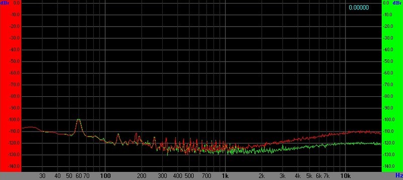
Flat Preamp, Stanton 681 Source, NJM2068DD (Green) versus OPA1612 (Red)
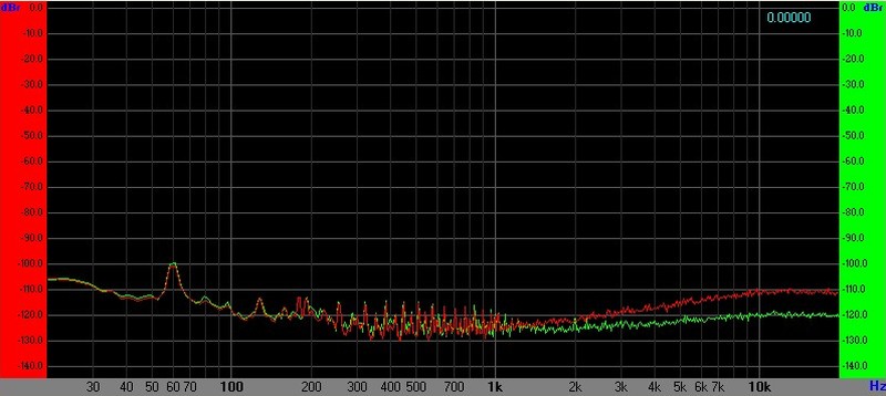
Flat Preamp, Stanton 681 Source, OPA2134 (Green) versus OPA1612 (Red)
Originally Posted by mediatechnology View Post
I mention it here because it illustrates the advantages to forcing uncorrelated noise sources into common mode. A majority of the noise voltage from uncorrelated current noise develops in common mode (as well as DC bias current offset) where it can be rejected.
You'll have to explain that one to me. From your schematic (1510 DS) the offset current flows through one or the other 1k resistors (absent any source impedance) no matter what the value of the 22k resistor is (even 0). Same with the uncorrelated noise. Changing an uncorrelated quantity to a correlated one with no apriory knowledge would require a Maxwell's demon I'm afraid.
Perhaps I wasn't clear. Absent source impedance bridging the input the 1K/22KRcm/1K network will be quieter than the equivalent input having 22K bias resistors. In other words the differential impedance of one is about 2K versus a differential impedance of 44K. You are correct that a 2K pair of resistors to ground will have the same Ios offset and Inoise as 2K/22K/2K. The point is that the common mode impedance can be increased significantly - assuming CMR is realized - without the penalty of scaling bias resistors. The majority of the Ib current, not the Ios, (and what correlated Inoise exists) develops across Rcm and gets stripped out by CMR. The uncorrelated noise and Ios does not.
The benefit is increased LF CMRR given the same amount of capacitor value mismatch and differential impedance.
When the source impedance is introduced bridging Rbias X2 or T-bias the uncorrelated noise becomes progressively correlated as the impedance is lowered due to shunting.
Reducing Xc - by eliminating it - as well as increased CMRR is one of the reasons I direct-coupled. At DC the source impedance of the balanced input phono preamp is that of the cart's Rdc||47K or about 600Ω. If it had two coupling caps it would be 47K at DC.
Last edited:
Douglas,
The fact that the current that is compensating both sides if the input pair has a degree of correlation according to SW, explains why a single resistor generates more noise than 2 resistors with half the value.
So after all it seems that you were right in thinking that this was he reason.
It degrades the total noise figure somewhat, but it still remains a good opamp for an MM preamp.
Hans
P.S. I will make a fresh simulation with this correlated CC feature
How did this thread go from a conventional filter solution to arguing about Ib noise and proper termination/coupling for cartridges?
That most recently occurred back at post #202.
I think it somehow began here to which I plead innocence: http://www.diyaudio.com/forums/anal...umble-filter-douglas-self-19.html#post4753032
Some I'm thinking we may be in the mood to return back to Warp/Rumble filtering?
I left off here: http://www.diyaudio.com/forums/anal...umble-filter-douglas-self-22.html#post4888547
Last edited:
@ Douglas Self: I think the issue is whether the input current noise of the opamp is 'the' input current noise which includes whatever mechanism there is to generate it. Bias current cancellation might be one of these mechanisms, but there should not be any reason to single it out and use as a separate noise source.
Or am I missing something here?
Jan
Hello Jan. Every opamp has voltage and current noise because of the basic operation of the output devices, but as I see it the bias cancellation currents are an extra noise mechanism on top of that. The standard wisdom is that the two bias cancellation currents are completely correlated, so equal input impedances would cause this to cancel. The basic current noise for each input is completely uncorrelated and so adds rms-fashion; they are quite different mechanisms.
However downthread Scott Wurcer says the bias cancellation currents are not completely correlated after all, so even with equal input impedances the OP27 would be noisier unless those impedances were very low. It's a long time since I did the measurements but as I recall the OP27 was 4 to 5 dB noisier than a 5534A with an average cartridge load.
In my last post on the subject of differential warp filtering I explained how encoding Left and Right into Mid Side could be used to filter Vertical warp signals.
See: http://www.diyaudio.com/forums/anal...umble-filter-douglas-self-19.html#post4753032
And also: http://www.diyaudio.com/forums/anal...umble-filter-douglas-self-22.html#post4888547
The process of performing Elliptic Equalization in mastering is identical to differential warp filtering. If a recording has large amounts of LF difference information it cannot be cut at an acceptable overall level due to high level vertical modulation. Many engineers simply do not mix this way but some material requires it. Thus, most all vinyl recordings are mono at LF to some degree. On playback, warp produces significant vertical modulation and there is very little desirable LF material in the difference signal.
When a multi-order filter is used to high pass filter side and MS is decoded into L and R peaking will occur in Left and Right. The mono sum however remains constant. A single-order filter does not peak.
An Allpass correction filter in Mid compensates the delay of the multi-order Side filter. This eliminates peaking and more importantly provides a symmetric response and a steeper, less-invasive, crosstalk curves.
MS encoding and decoding is not hard to do with high precision:
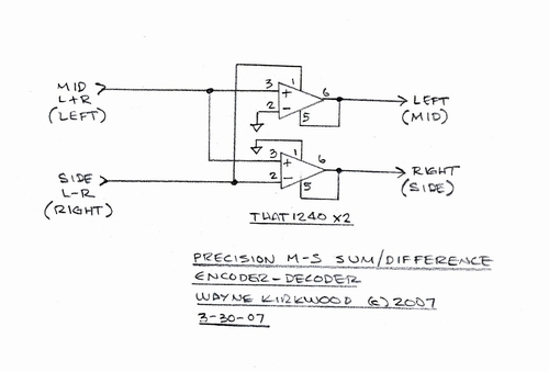
Balanced line receivers provide precision summation and differencing.
The same circuit provides both encoding and decoding.
The internal resistors are trimmed to within 50 ppm ratio match and track with temperature.
The mid output for identical inputs has +6dB gain.
The decoded outputs produce 2L and 2R.
The inputs must be driven by 0Ω op amp outputs to maintain precision: Any impedance in series with an input appears as part of the matrix.
A practical MS implementation with fully-balanced I/O looks like this:
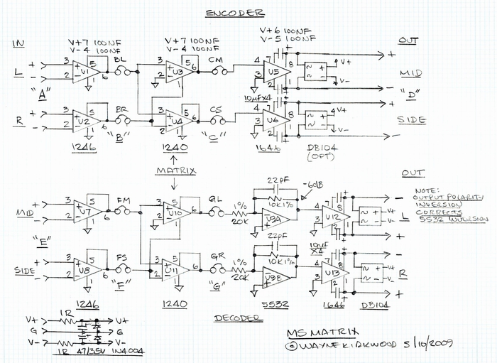
U3 and U4 are the MS encoders; U10 and U11 decode MS into L and R.
For a warp filter only we do not need U5-U8 to balance the inserts. U12 and U13 are also optional.
In the MS domain gain accuracy is king. Any gain error reduces separation.
U9A/B attenuate the signal in the LR domain to scale 2L and 2R back to L and R.
With all the ICs installed and the insert looped through broadband crosstalk numbers of >-70dB are not uncommon. The overall gain is unity.
The Mid and Side filters are inserted between points "C" and "F."
The second-order filter.
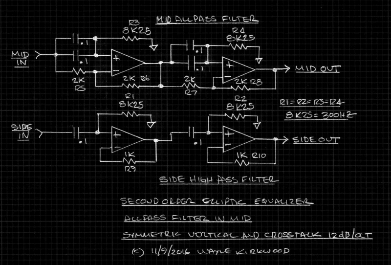
The test filter was designed for Elliptic EQ and will be tuneable by varying R1-R4. A 300 Hz frequency was chosen for my tests which is the highest setting for a Neumann EE-77 first-order EE.
A chose cascaded 6dB/octave sections for the side filter for a number of reasons.
I wanted all of the tuning resistor values to be equal. Most mastering engineers want stepped controls with up to 24 positions. Having all of the four decks have the same values simplifies construction.
The cascaded second-order HP sections are monotonic with an asymptote that approaches a precise unity gain in the passband.
R9 and R10 exist to prevent voltage follower latch-up with bipolar op amps having differential input diodes.
The Allpass filter operates in the Mid path to correct the Side HP filter. The capacitors are made double to match the HP response's phase.
R5-R8 are made 2KΩ to present a 1KΩ Thevenin equivalent to the inverting input. This equalizes the slight phase error introduced by R9 and R10.
The result is a filter and crosstalk plot that looks like this:
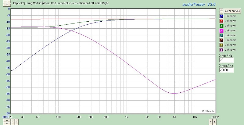
Mono is flatline.
Vertical (side) rises at 12 dB/octave.
The crosstalk curve falls at 12 dB/octave.
There is no peaking.
(The rise at 5kHz was with 10KΩ feedback resistors and later corrected.)
Side can be high pass filtered at a very high frequency making orders >2 unnecessary to remove significant amounts of vertical warp. A huge swath of low end difference (warp) can be removed without harm.
With vertical signals removed, relatively gentle HP filtering of left and right can be used to eliminate any remaining Lateral warp and rumble.
The discussion thread for this circuit is located here: Pro Audio Design Forum • View topic - A Second Order Elliptic Equalizer for Vinyl Mastering
On the third page is a link to sound files (74 MB) of it being used in the context of an EE. The object of those files is to see what its sonic footprint is for wide sources.
We'll see what the mastering engineer says...
Remember that this circuit is constructed on a Protoboard and there were clip leads involved. Be kind.
See: http://www.diyaudio.com/forums/anal...umble-filter-douglas-self-19.html#post4753032
And also: http://www.diyaudio.com/forums/anal...umble-filter-douglas-self-22.html#post4888547
The process of performing Elliptic Equalization in mastering is identical to differential warp filtering. If a recording has large amounts of LF difference information it cannot be cut at an acceptable overall level due to high level vertical modulation. Many engineers simply do not mix this way but some material requires it. Thus, most all vinyl recordings are mono at LF to some degree. On playback, warp produces significant vertical modulation and there is very little desirable LF material in the difference signal.
When a multi-order filter is used to high pass filter side and MS is decoded into L and R peaking will occur in Left and Right. The mono sum however remains constant. A single-order filter does not peak.
An Allpass correction filter in Mid compensates the delay of the multi-order Side filter. This eliminates peaking and more importantly provides a symmetric response and a steeper, less-invasive, crosstalk curves.
MS encoding and decoding is not hard to do with high precision:
Balanced line receivers provide precision summation and differencing.
The same circuit provides both encoding and decoding.
The internal resistors are trimmed to within 50 ppm ratio match and track with temperature.
The mid output for identical inputs has +6dB gain.
The decoded outputs produce 2L and 2R.
The inputs must be driven by 0Ω op amp outputs to maintain precision: Any impedance in series with an input appears as part of the matrix.
A practical MS implementation with fully-balanced I/O looks like this:
U3 and U4 are the MS encoders; U10 and U11 decode MS into L and R.
For a warp filter only we do not need U5-U8 to balance the inserts. U12 and U13 are also optional.
In the MS domain gain accuracy is king. Any gain error reduces separation.
U9A/B attenuate the signal in the LR domain to scale 2L and 2R back to L and R.
With all the ICs installed and the insert looped through broadband crosstalk numbers of >-70dB are not uncommon. The overall gain is unity.
The Mid and Side filters are inserted between points "C" and "F."
The second-order filter.
The test filter was designed for Elliptic EQ and will be tuneable by varying R1-R4. A 300 Hz frequency was chosen for my tests which is the highest setting for a Neumann EE-77 first-order EE.
A chose cascaded 6dB/octave sections for the side filter for a number of reasons.
I wanted all of the tuning resistor values to be equal. Most mastering engineers want stepped controls with up to 24 positions. Having all of the four decks have the same values simplifies construction.
The cascaded second-order HP sections are monotonic with an asymptote that approaches a precise unity gain in the passband.
R9 and R10 exist to prevent voltage follower latch-up with bipolar op amps having differential input diodes.
The Allpass filter operates in the Mid path to correct the Side HP filter. The capacitors are made double to match the HP response's phase.
R5-R8 are made 2KΩ to present a 1KΩ Thevenin equivalent to the inverting input. This equalizes the slight phase error introduced by R9 and R10.
The result is a filter and crosstalk plot that looks like this:
Mono is flatline.
Vertical (side) rises at 12 dB/octave.
The crosstalk curve falls at 12 dB/octave.
There is no peaking.
(The rise at 5kHz was with 10KΩ feedback resistors and later corrected.)
Side can be high pass filtered at a very high frequency making orders >2 unnecessary to remove significant amounts of vertical warp. A huge swath of low end difference (warp) can be removed without harm.
With vertical signals removed, relatively gentle HP filtering of left and right can be used to eliminate any remaining Lateral warp and rumble.
The discussion thread for this circuit is located here: Pro Audio Design Forum • View topic - A Second Order Elliptic Equalizer for Vinyl Mastering
On the third page is a link to sound files (74 MB) of it being used in the context of an EE. The object of those files is to see what its sonic footprint is for wide sources.
We'll see what the mastering engineer says...
Remember that this circuit is constructed on a Protoboard and there were clip leads involved. Be kind.
Last edited:
Not sure I follow. 20% correlated or 20% uncorrelated?
Here are some comparative measurements for the bias-current-compensated OPA1612 vs the NJM2068DD and OPA2134. The preamp is a fully-balanced instrumentation amp topology with double-balanced CM rejection. This is with a real cart on a real arm sitting on a turntable about four feet from a dimmer. About as real-world as it gets.
20% correlated or correlation coefficient of 0.2 rather than 1.0. This was one of my ancient exchanges with Jim Williams on data sheet minutia (re: LT1028), I even got Barrie Gilbert involved. You have to delve into the actual operation of a split collector PNP at the basic physics level. Comparing FET's to bipolar is apples to oranges, you would have to cut the Ib comp out and do the two measurements with and without on the same device. A fully balanced phono can be made with no hard DC path to ground on either side of the cart which IMO lessens the chance of catastrophic error current even more.
Last edited:
It's a long time since I did the measurements but as I recall the OP27 was 4 to 5 dB noisier than a 5534A with an average cartridge load.
The 5534 is almost a special case, whether by design or chance the collector current of the input devices is just enough to achieve its noise spec 4nV or so IIRC. Even without Ib comp amps that go for 1-2nv are going to have more Ib noise and high L MM cartridges are going to exhibit noise from this. Even without Ib comp the LT1028/AD797 would not be good choices for standard Stanton/Shure cartridges. 3, 4, 5dB degradation that's a good ballpark estimate depending on the weighting you use. Going bipolar vs. FET it gets up into double digit dB depending on the cart.
20% or correlation coefficient of 0.2 rather than 1.0.
OK, so they're essentially uncorrelated.
A fully balanced phono can be made with no hard DC path to ground on either side of the cart which IMO lessens the chance of catastrophic error current even more.
Indeed they can. It might look like the one that started this thread veer: http://www.waynekirkwood.com/images...utput_Moving_Magnet_Phono_Preamp_small_BW.jpg
And even though the dual op amps used to make them have, in an INA topology an Ios that is not specified between sections, they turn out in practice to have Ios spec similar to the op amp itself e.g. nA not uA. That "specification" is not "guaranteed" but one thing that is guaranteed is that all of the transistors were made on the same day and match pretty closely.
I have customers build this unbalanced and I can't understand why they don't take advantage of it. It being balanced (and flat) is the only magic.
Last edited:
How did you allow for the noise from the bias cancellation system?
I added a bias current cancellation noise source of 0,35pA/rtHz, giving me exactly the same noise figures with the 10 Kohm / 0 Ohm and 5 Kohm / 5 KOhm resistors as in the AD specs.
With the cart connected and now adjusted for Bias Current Cancellation, no dramatic changes took place:
Weighted SNR went down from 79.4 to 78.8 dBA with BCC
Unweighted SNR went down from 76.6 to 76.1 dB with BCC
Taking the 5534A from TI, being the lowest noise version with,
en=3.4nV/rtHz enk=48Hz in=0.31pA/rtHz and ink=660Hz gave the following figures with the Cart connected:
Weighted SNR 80.3 dBA
Unweighted SNR 77.2 dB
So yes the OP27 is just slightly noisier because of higher current noise, but both OPA's seem to be perfectly suited for using in a MM Riaa preamp.
Hans
Last edited:
So yes the OP27 is just slightly noisier because of higher current noise, but both OPA's seem to be perfectly suited for using in a MM Riaa preamp.
Hans
The datasheets vary a lot from manufacturer to manufacturer almost 2 to 1 in some cases. TI's test jig and formula assumes ALL the Ib noise is correlated which is not possible. I hope this point has not been missed, the input device noise is always uncorrelated from it's Ib comp current it's only the two Ib comp currents that are supposedly correlated to each other. for a single ended application it does not matter the Ib noise is simply 3dB more with Ib comp.
The datasheets vary a lot from manufacturer to manufacturer almost 2 to 1 in some cases. TI's test jig and formula assumes ALL the Ib noise is correlated which is not possible. I hope this point has not been missed, the input device noise is always uncorrelated from it's Ib comp current it's only the two Ib comp currents that are supposedly correlated to each other. for a single ended application it does not matter the Ib noise is simply 3dB more with Ib comp.
Hi Scott,
Yes I inserted Bias Current Compensation that was 100% uncorrelated to Ib. And yes that resulted in an Ib being 3dB stronger for the almost single ended MM application.
Hans
Hi Scott,
Yes I inserted Bias Current Compensation that was 100% uncorrelated to Ib. And yes that resulted in an Ib being 3dB stronger for the almost single ended MM application.
Hans
Makes sense, I just wonder about the datasheet numbers considering I'm not sure there are not some bad assumptions in measuring the specs.
@ Hans Polak
Thanx for the calculations & info etc 🙂 It seems i made a wise choice in the OP27's 😉
As you showed, the NE5534 is still a good candidate despite its age. And the fact that it was available originally All those years ago, is a testament to Excellent design & production work !
@ mediatechnology & scott wurcer
Thanx for your posts with good info etc too 🙂
- Status
- Not open for further replies.
- Home
- Source & Line
- Analogue Source
- What is the ideal conventional rumble filter?- Douglas Self