hi gents, yes I searched...
can anyone help with schematics or even better, with service manual for sanyo plus t35 tuner?
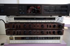
I recently obtained both, preamp c55 and tuner t35 from flea bay, and I am working on restoration
Preamp did not need much, just cleaning the switches and pots with deoxit, it works great and sounds good even before recaping. It has four bipolar caps in signal, which I am going to replace eventually. But I could not wait, I needed to test it, you know how it goes...
When it comes to the tuner, it works, but its little more complicated as preamp. Signal meter needs adjustment, as it shows relatively full signal on the indicator, even station is far and signal is small, which is not convenient for antena positioning. Then it needs a little adjustment, as the "lock" function turns in when tuning indicator is not fully in the center, and so on. Otherwise it sounds good on strong stations. I would like to have schematics, as to identify which pot and which coil is for what. I do not want to just jump in and start touching the stuff. Plus I would like to see audio section after stereo decoder, as what caps potentially should be replaced.
Schematics would be helpful, service manual even better.
Thanks, ed
can anyone help with schematics or even better, with service manual for sanyo plus t35 tuner?
I recently obtained both, preamp c55 and tuner t35 from flea bay, and I am working on restoration
Preamp did not need much, just cleaning the switches and pots with deoxit, it works great and sounds good even before recaping. It has four bipolar caps in signal, which I am going to replace eventually. But I could not wait, I needed to test it, you know how it goes...
When it comes to the tuner, it works, but its little more complicated as preamp. Signal meter needs adjustment, as it shows relatively full signal on the indicator, even station is far and signal is small, which is not convenient for antena positioning. Then it needs a little adjustment, as the "lock" function turns in when tuning indicator is not fully in the center, and so on. Otherwise it sounds good on strong stations. I would like to have schematics, as to identify which pot and which coil is for what. I do not want to just jump in and start touching the stuff. Plus I would like to see audio section after stereo decoder, as what caps potentially should be replaced.
Schematics would be helpful, service manual even better.
Thanks, ed
I'm afraid I can't help with the manual, but just a thought on the signal strength meter... it was pretty common generally for these to show full strength, and for the simple reason that it always looked better on the shop shelf to prospective customers that way.
If you need to identify coil functions then it can sometimes be worth just threatening them with a ferrous trimmer... no need to alter anything... just put it into the dust core and observe the effect as the trimmer tunes/detunes the coils.
If it uses a recognised chip set (rather than all discrete) then any application notes should show virtually a standard implementation and what any coils and presets do.
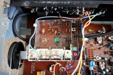
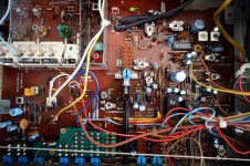
hi Mooly, thanks for reply, yes, that's the way its going to be, most likely. But it is going to be quite easy. Looking inside, these are the chips I see: A1231N (if section), HA1196 (stereo demodulator), LB1416 (signal level meter), TC4011BP, LA1240, and output dual opa rc4558.
Last chips are likely AM section, which I do not care about...
The reason I think the adjustement is going to be easy, because each pot is labeled what it is for!
Right next to A1231N I see 3 ceramic filters, two big poted coils for demodulation, and most importantly IF gain pot, Mute 1 pot, Mute 2 pot, and FM signal pot.
Right next to HA1196 I see 76kHz adjust, and two pots sep. wide and sep. narrow...
So over the weekend I will spend more time with it. I see its going to be fun.
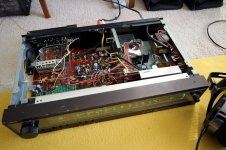
It is well built 4 gang analog tuner, with analog scale plus digital readout, which slides under analog scale, as you tune in. Quite a nice looking tuner.
Offcourse there is board for digital display and so on...I do not care about that.
I can take some pictures, if forum is interested.
Last chips are likely AM section, which I do not care about...
The reason I think the adjustement is going to be easy, because each pot is labeled what it is for!
Right next to A1231N I see 3 ceramic filters, two big poted coils for demodulation, and most importantly IF gain pot, Mute 1 pot, Mute 2 pot, and FM signal pot.
Right next to HA1196 I see 76kHz adjust, and two pots sep. wide and sep. narrow...
So over the weekend I will spend more time with it. I see its going to be fun.
It is well built 4 gang analog tuner, with analog scale plus digital readout, which slides under analog scale, as you tune in. Quite a nice looking tuner.
Offcourse there is board for digital display and so on...I do not care about that.
I can take some pictures, if forum is interested.
Nice pickup on that pair...
I have a T55 tuner from the plus series that I often use to test out gear (it has variable output level). The T35 is supposed to be a good sounding tuner and the preamp is also supposedly pretty good, although I haven't owned either one.
If you look around on the web you should be able to find copies of the service manuals for both.
Hi Ed,
Without the proper equipment, you shouldn't touch the tuner. If it works, let it be, or have it aligned properly.
As for the improvements, start with the detector output capacitor(s), then look at the audio capacitors. With a 'scope these will be easy to find. Of course, this wouldn't be a complete "recap" (I hate that term). Same holds true of the preamplifier and especially the amplifiers. You are best not to touch an amplifier. There are some nasty surprises lurking in there, and if you do not have an oscilloscope - don't mess around in there. The amp can run and still have a problem. Some times a big problem.
I get a lot of "just recapped" equipment for repair. They are sort of TIM problems.
Technician Induced Malfunction
-Chris
good advice anatech, i will keep that in mind
I see four electrolytic capacitors what seems like in and out of dual output opa
those would be the only one to replace
Otherwise the pot labeled "fm signal" is precisely what i was looking for, it does not change alignment, only sets the sensitivity of signal meter
i already lowered to the level, where the strongest stations are full signal, all others show less then full
as it was before all stations were in full signal no mater how weak or noisy
I will not touch any critical alignment, i just need to make sure when it does "quartz lock" it is precisely tuned...that needs to be figured out.
The reason I think the adjustement is going to be easy, because each pot is labeled what it is for!
Marked pots are always a bonus
") The 4558 would certainly be something to look at changing... I'm assuming its the audio line output amp and not used for PSU or other duties. Perhaps something like an NE5532 or LM4562.
The 4558 would certainly be something to look at changing... I'm assuming its the audio line output amp and not used for PSU or other duties. Perhaps something like an NE5532 or LM4562.I have not decided, but if I will feel like it, besides those four caps, I may install the socket for the output dual opa chip, that way I can swap to any, but I do not see it completely necessary, as of now the tuner sounds quite decent.
As I have Sony ST-S555ES (I have 3 of these!) as my reference, and Sanyo Plus t35 will never reach the level of Sony no matter what I replace or tune, I may just leave the 4558 in.
Sanyo sounds great on strong signals, and mono on weak signals, but does not come close to the Sony when it comes to the weak long distance stations. And that is a fact.
Now when it comes to the signal meter, Sanyo t35 has only 5 led signal strenght indicator, which, even now working fine, is far cry for good signal meter. Sony has way better signal meter, something like 30 bar signal meter (I am not at home now, its just what I recall). Similar to some Yamaha models, remember those signal meters?
But, but, when it comes to the signal strenght meter, nothing compares to better JVC tuners. I have one, X300?, do not recall now exactly, they do measure signal in digital readout in dB from 0 to 100 dB in one dB scale. Amazing. Now when it comes to signal quality, and sensitivity, JVC does not even come close to Sony, that's for sure, but I keep it just for the signal level meter. And one other feature, two separately powered AC switches, which can be programmed. Quite a useful feature...now back to work.
Last edited:
Hi Ed,
If you were to replace the 4558, use the NE5532. An LM4562 would be wasted in there while the NE5532 will maybe clean up the mids a little.
Reducing the sensitivity of the signal meter was a good call. That makes the tuner a lot more usable. The JVC and Sony might be improved with new, matched ceramic filters. This would increase the sensitivity of any tuner you replace them in. Their losses can be very low compared to earlier filters, and their bandpass shape is often much better as well (reduction in THD).
-Chris

Hi Ed,
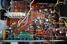
You have a three section tuning cap for FM, one is for the local oscillator. That brings the total number of sections to four.
To me, that doesn't look like a bad tuner at all. Does it have a narrow - wide filter setting? You may actually have a 4 section IF filter set there. Each filter has a number on it that tells you what the width of the pass band. You can cross reference the number to the value. Common filters are 250 KHz, 280 KHz and 330 KHz.
-Chris
A surprising number of presets for a tuner like that. Maybe all those little 'screw things' need tightening up
Its important that all the ceramic filters have the same 'colour spot' if you replace them (same as in all matching such as red spot, white spot etc) as that specifies the centre frequency. Doesn't matter what colour you fit but they they must all match.
Come to think of it, I don't think I've ever had need to replace one. And change that 4558 they are horrible.
Its important that all the ceramic filters have the same 'colour spot' if you replace them (same as in all matching such as red spot, white spot etc) as that specifies the centre frequency. Doesn't matter what colour you fit but they they must all match.
Come to think of it, I don't think I've ever had need to replace one. And change that 4558
they are horrible.Done and done (sorry Chris, i put the socket in), and ne5532 is big improvement, day and night. Not a placebo, thats why i put a socket in.
Now it definitely sounds better than jvc. It replaced jvc in one bedroom system, and with matching preamp it even looks cool.
Now i have spare Nikko beta III (all fet) preamp. Anyone in the market for great preamp? Just kidding.
Thanks for the help everyone.
Now it definitely sounds better than jvc. It replaced jvc in one bedroom system, and with matching preamp it even looks cool.
Now i have spare Nikko beta III (all fet) preamp. Anyone in the market for great preamp? Just kidding.
Thanks for the help everyone.
- Status
- This old topic is closed. If you want to reopen this topic, contact a moderator using the "Report Post" button.
- Home
- Source & Line
- Analogue Source
- sanyo plus t35 tuner