Hi Ed,
The sockets are an added point of connection failure. They also add capacitance to the connections. In this particular application you don't need to worry about that. Hopefully the connections in the socket will not give you trouble.
Did you use the turned Augate style, or the flat spring connection like the (cheap) TI sockets? Augate style sockets are the most reliable. l'm only trying to save you future problems Ed. Your decision doesn't affect me at all.
-Chris
I understand perfectly Chris, you are off course right. Sockets are not the best thing, but they give you fun swapping op amps quickly.
I think i used one of those generic sockets, i have some gold plated with oval holes, but here i used cheap stuff. Where you slide legs between two plates.
Anyway, i touched carefully and adjusted those two coils in demodulator, and now it locks in perfectly in the middle and on strong and weeks stations all the time. That's it. I am done for now. Listening to good strong radio station (like 89.3 jazz now G-strings...) in stereo is a pleasure...
Hello my friends,
Could someone help me with my radio tuner? I also have a sanyo plus t35, and until recently I rarely used it. But recentIy I decided to give it life again, as it is a very good tuner.
I'm facing this problem: when I want to tune in to the correct frequency of a radio station, eg 96.10 fm, the Green LED doesn't light, except the Red LED on the lower side of the frequency. The Green LED of the frequency lights up only when I set the frequency to 96.15 fm and then the last digit of the frequency starts blinking between 0 and 5 (ie between 96.10 to 96.15). the second I notice is that the red led of the Lock Indicator doesn't turn on or illuminates briefly when turning the dial knob. Αll this happens at all station frequencies, (for example if the correct frequency is 101.50 -> green led lights on 101.55, or the correct frequency is102.80->green led lights on 102.85 etc).
ps: probably some adjustment is needed. I have a look at the service manual, but because I'm not sure what to do, I would be grateful if someone could help me.
Post a detailed pic of the internals and I will tell you which adjustment will fix your problem.
Given the symptom you are describing, it is out of alignment. You don't have an FM stereo generator and audio analyzer so a service manual is not going to be that useful. My instruction will re-center the tuning.
Where are located?
Given the symptom you are describing, it is out of alignment. You don't have an FM stereo generator and audio analyzer so a service manual is not going to be that useful. My instruction will re-center the tuning.
Where are located?
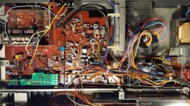
Thank you ej25awd for your quick response. Here are some pictures of the internal, and the service manual (just in case). ")
Attachments
-
 20190227_013449-2124x1195.jpg766.9 KB · Views: 105
 -
 20190227_023736-768x1365.jpg324.7 KB · Views: 104
 -
 20190227_023755-768x1365.jpg278.3 KB · Views: 110
 -
 20190227_023842-768x1365.jpg377.4 KB · Views: 116
 -
 20190227_023859-768x1365.jpg386.3 KB · Views: 119
 -
Sanyo PLUS T35 - Service manual.pdf746.5 KB · Views: 100
Thank you ej25awd for your quick response. Here are some pictures of the internal, and the service manual (just in case).
Thanks for the service manual. Unfortunately, the copy you've uploaded has been compressed to the point that the schematic is unreadable. In general if you can find the service manual on the net, others can too
Now let's proceed. Just follow the steps below and practice safety.
0. Get hold of a DMM, preferably use test leads that have grabbers/clips. If you have the regular tips and a steady hand, it will work too.
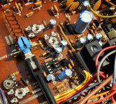
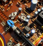
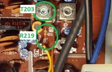
1. Remove tuner top cover screws to allow access. Pop open the cover and locate T203 and R219.
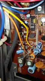
First thing to look for is the shape of the ferrite core as seen on the T203 top center. T203 transformer is the metal can one closest to LA1231N IC. I would imagine the T203 slot to be around 1-2mm long and less than 1mm wide. Note the dimensions of the T203 slot for step 2.
The other one you are looking for is R219, this is where you will hook up your DVM to measure the DC voltage later. Set your DVM to 199mV range or similar later. One of the picture you've attached shows a brown/orange and yellow wire wrapped on metal posts with "(10)" and "(7)" silkscreen legends respectively. Use the metal posts later as anchor points for your grabbers/clips. It doesn't matter where the positive and negative leads go.
2. Prepare your DIY adjustment tool. My preference is a bamboo chopstick. With a sharp knife, fashion a flat screw driver with a tip that will fit T203 ferrite core slot. You need a tool that has enough torque and strength, a material that is softer than the ferrite core. A metal screw driver will not work, since it WILL alter the magnetic properties of the ferrite core when it comes to close contact. The other issue with a metal/ceramic screw driver is that their strength/hardness is equal or greater than the ferrite core that the likelihood of the damaging the core itself is a possibility.
3. Replace the top cover, connect antenna to rear FM antenna connector then power up the tuner.
5. Set tuner to FM mono, locked off, REC level off, IF band wide, muting off, Tune to a strong station near the center of the dial. Tune for maximum strength as shown on signal strength meter. Ignore the center tune LEDs, we'll fix this later.
6. Leave tuner on for 15-30 minutes to warm up. Re-tune after 30 minutes if the signal strength varied. To accelerate heating, cover the unit with a towel. I don't know your location, if you are in a temperate zone the towel will speed things up.
7. Pop the top cover, make sure the tuning knob is not disturbed and go ahead and hook up your DVM to posts "10" and "7", again polarity doesn't matter. Note the voltage, if it is less than +10mV or -10mV DO NOT touch T203! If it is outside these limits, proceed with the adjustment of T203 SLOWLY with the new tool you just made and target a DC voltage value of close to zero/0 volts. A few degrees of turn will be significant so do this slowly and note the direction of the voltage polarity and make corrections with the direction of your rotation if it goes the other way.
8. If the step 7 adjustment resulted in the green tuned LED to be lit then your job is done, power off the tuner and put everything back together. If not then you have bigger problems and we'll deal with this later.
Attachments
Thank you very much ej25awd. Your instructions and the steps you propose are very helpful and clear. Fortunately, I have a DMM, I will try to make a screwdriver or I will buy one to proceed to the process you describe. I will proceed as soon as possible. I thank you again for the time you spent here helping me out.
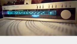
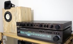
Dear friend, thank you again for your valuable help. I just completed the procedure you suggested me. The radio tunes perfectly now to the frequencies of all the radio stations. I send you a picture. Everything works perfectly!
Excellent!
I'm glad to help in sorting out the tuned lock indicator issue.
- Status
- This old topic is closed. If you want to reopen this topic, contact a moderator using the "Report Post" button.
- Home
- Source & Line
- Analogue Source
- sanyo plus t35 tuner