18V and your model explains it. But mainly 10R answers it.
Too much CGS I would think, about 30 is nearer for it maybe gives you more THD in sim than in reality.
But the JFet model parameters and the actual Spice model for them aren't very reliable. If its Ok in the build, we are alright. And it seems OK from what you measure. Spencer matches are reported good in the long run too.
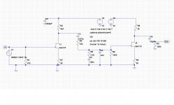
You can expect 7.6V at the drains, 51dB gain, and the curve in the attachment. The 6.8mA matched look pretty OK in this circuit. I used 30m beta in the sim for them. 51dB is good for 1mV cartridge.
Hi Salas,
My cart is a new-old-stock Shure M75 ED Mk2, the biggest selling cart of the 1970s, and considered at the time to be a bargain, though nothing special I guess.
It has 5mV output. 5 times what you say will be OK with my current circuit. How might I adjust the circuit to allow for that? Do MM carts go as low as 1mV output?
Many thanks
Lucas
You can put 50R trimmers between each source pin and ground, get HFNRR test disc, play 3rd track -20dB pink noise, hook up the DVM set for AC RMS on each channel's output, and by starting at half point, get it to match 50mV for each output. That is 500mV 0dB i.e. 40dB gain on 5mV cart. See that the trimmers are producing about the same region DCV across drains and ground between channels and positions. Maybe you gonna end up around 27R for each trimmer with your Idss. Check the TT with the test disc while you are at it too. Good luck.
Salas,
Can you guide me to some good quality caps for this circuit? Anything from mouser and digikey, but not something that costs tons of money. I've heard the mkt (square ones) caps to be good.
Lucas,
I posted a circuit some posts ago which I modified for my 7.8mV cart. Maybe you could try that. I'm not guaranteeing success, but it worked for me.
Wow. That sounds complex. I was hoping to avoid all that kind of sorcery when I picked this RIAA. Maybe I should have got some GR fets after all.
Not sorcery, it is the simplest you can do without generator and scope. OTOH you may just up the source resistors to 27R and compare the level and the sound with the ones already installed for GR. If still loud enough, go 33R.
Salas,
Can you guide me to some good quality caps for this circuit? Anything from mouser and digikey, but not something that costs tons of money. I've heard the mkt (square ones) caps to be good.
Look for Vishay and Wima polypropylenes, also Koa Speer resistors in Mouser.
Not sorcery, it is the simplest you can do without generator and scope. OTOH you may just up the source resistors to 27R and compare the level and the sound with the ones already installed for GR. If still loud enough, go 33R.
Thanks Salas. Duh! Which are the source resistors?
Thanks, Lucas
ok, so could I trial and error it, starting with 27R? I don't have a test disc, or a good enough knowledge of test procedures to really trust myself without a guiding hand looking over my shoulder. If the spice suggests 27R, then I'd be happy to go with that. I'd only raise the alarm if it sounded awful I guess.
Many thanks
Lucas
Many thanks
Lucas
Salas,
I was trying more configurations with the load resistors etc. I found one with 16V first stage and 24V second stage. The distortion dropped to 0.08%. I built it and it sounds better in every way except it has become very hot... in the sense that it is picking up the clicks and pops too strongly and there is some electrical noise as well. I put 520uF caps before the load resistors and ground and the noise went away for a while, but its back again now.
I tried changing the input resistor and it changes the sound, for good and bad depending on value, but i couldn't get rid of the noise. Apart from the noise, this is a winner. What gives?
Attachments
The second stage is the main THD contributor in such a circuit because it handles some appreciable level. You gave it better swing and degeneration now. That is well. You have two floating psus (batteries) as I understand on it now? One 16V and one 24V? Use just the 24V one, put a large electrolytic across it, right on its poles. Then from the B+ node on the circuit use 2 resistors towards the stages drains. 100R for the second stage, 2k2 for the first stage. Leave the local drain to earth caps you used there. See that your 1st stage drain voltage is around 15-16V or change that 2k2 a little (you did not give me bias current data but it should be around 4mA?). That experiment may save the you the susceptibility problems, else its something else.
ok, so could I trial and error it, starting with 27R? I don't have a test disc, or a good enough knowledge of test procedures to really trust myself without a guiding hand looking over my shoulder. If the spice suggests 27R, then I'd be happy to go with that. I'd only raise the alarm if it sounded awful I guess.
Many thanks
Lucas
I can't suggest more than a simple trial and error test given the limitations you sincerely admitted for performing adequate technical procedures. Wishing success then. Cheers.
I was looking at your simplistic njfet riaa and you commented at the start that this type of circuit should not be used for mm. You recommended cascoding the input jfet. Can you please post a schematic of such a circuit? All the ones in that thread appear as black bkgnd with blue lines... :|
Discounting batteries, as I imagine them to be inconvenient, what kind of power supply should I use for this circuit? I am currently looking for a 2x 24-28v regulated supply, as i assume this is the best thing. I imagine that the current draw is quite tiny on this circuit. I would like something physically small, yet effective. Can anybody suggest a design, or kit from eBay, or whatever please.
Many thanks
Lucas
Many thanks
Lucas
Hi Lucas
Try this one: http://www.diyaudio.com/forums/analogue-source/129126-simplistic-njfet-riaa-249.html#post1948792
Ricardo
Try this one: http://www.diyaudio.com/forums/analogue-source/129126-simplistic-njfet-riaa-249.html#post1948792
Ricardo
Hi Lucas
Try this one: http://www.diyaudio.com/forums/analogue-source/129126-simplistic-njfet-riaa-249.html#post1948792
Ricardo
Wow! Even more K170s! How many can one cram into a hifi? I have 2 in the phono stage and 4 in the buffer already. It looks a touch complex. Is it? Is there a layout plan for p2p or a PCB anywhere? Have you built one?
Many thanks
Lucas
- Home
- Source & Line
- Analogue Source
- Ultrasimple MM/MC RIAA preamp 2