I just replaced the KSA992 in the supplemental current source (the one that actually carries the current) for the input stage with 2SA965. This is a TO-92L vs. a straight TO-92, so there should be lower temperature rise. I don't know if that will affect the drift in VDS, as I think that will be more influenced by the sensing transistor of the ring-of-two current source.
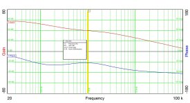
I finally got to scan the RIAA preamp sections of this preamp after a humiliating experience last weekend (locked myself out of the lab and had to slink home in disgrace...). Match between channels is not quite as precise as earlier versions of this amp, but still OK.... I think wat happened in this case was I was only able to match the PN4341-based 2nd section of this preamp at the max current capability of my sorting jig, which is ~15 mA. Actual bias current was more, so the second stage gain elements likely had a less precise matching at the higher bias current vs. the max 15 mA of the sorting jig. I think that I will go back into the jig and mess with the bias resistors on my reference so I can get at least 30 mA capability. 0.58 dB of difference between channels at 1 kHz is still not all that shabby.
Attachments

Last edited:

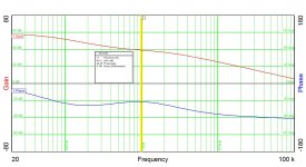
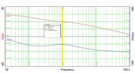
Here are the results from this afternoon's G-P scan. I found that I had used 4.53k instead of 4.32k as the gain resistor on the 2nd stage of channel 2. Using the proper value of gain resistor (and a bit of rebiasing) reduced gain mismatch between channels to 0.25 dB, down from 0.58 dB.
Attachments
- Home
- Source & Line
- Analogue Source
- Ultrasimple MM/MC RIAA preamp 2