Hi guys
i have 8x Linear Systems lsk170 a grade see pic
would these be any good for this mm phono ?
 20201109_200237 by glenn jarrett, on Flickr
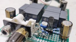
i have 8x Linear Systems lsk170 a grade see pic
would these be any good for this mm phono ?
20201109_200237 by glenn jarrett, on Flickr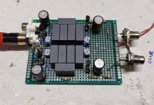
Bepone-
Re the distortion spectrum of the circuit I presented several pages ago...
I tried running a simulation of the full circuit at 1kHz, which would be appropriate for looking at distortion products, and it appears that the computer keeps running out of memory using a fine enough time resolution to make distortion results meaningful. What I had to resort to is to run each gain cell at 10 kHz to get good results that don't overwhelm system memory. I found out in the process that the J110 yields better distortion results than the J310. I'll post results for the first stage when I get the time. The J110 is still available NOS from a few surplus vendors. I may try an option using one of the 15V On Semi parts that look to be available stand-ins for the BF862.
I may try laying out a version of the circuit for old times sake an giving it a measure with my HP8903.
Here is a retooled version of the input cell from the circuit presented in post 369. It utilizes a J110 fet rather than the J310, as I was able to obtain lower THD with that device. The circuit uses a jfet cascode, I may go back to trying a bipolar cascode using a 2N4401 to see if I can get similar results. THD is close to what you can get using a 2SK/LSK 170 in the same position
The overall architecture is a first stage with gain of 40X followed by a passive RIAA filter and a 30X output gain cell. This is a compromise between noise performance and overload margin for the first stage. The 40X - RIAA-30X approach yields a 1kHz gain of ~40dB, optimal for a MM cartridge.
THD is shown for a 2mV input (typical MM level) and 0.2mV input (typical MC level). As you can see, the lower excitation level results in much lower THD, typical of an open loop Class A approach like this. Salas and I went round and round a bit re THD levels in my "All American" thread, with Salas reporting lower THD simulation results than mine. In retrospect, this was possibly due to Salas using typical MC levels rather than the 10X higher MM levels.
Next up will be a 30X second stage, analyzed with an input level sufficient for 1V output. The THD will be significantly lower for the current source augmented cascode than for a simple cascoded common source stage at an excitation level sufficient for 1V output. This was pointed out in the "All American" thread cited in post 369.
Attachments
Last edited:
thanks for the input, wrenchone.
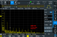
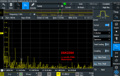
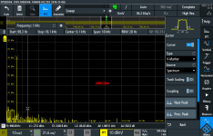
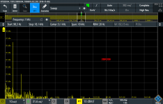
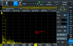
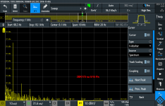
i made around 8 RIAA's (one valve, 7 FETs) in the past few weeks and verified by measurements + on ear. here are spectrum graphs of 4 versions, 3 like "Mads" Riaa from this thread, and one with BC550 in cascode with input FET.
spectrum analysis showing excellent behaviour of original 2SK170, 2SK170 + BC550 cascade and smd FET 2SK2394 . paralleled 2SK209 are not so ok in my findings, there is increased 2H (maybe it needs more time to adjust bias and pick better load , higher Rd- but no time to play again with at the moment). DC supply and Rs adjusted according to the used FET type. cascode version has a few (3?) dBs lower 2H and 3H , so maybe it is not necessary to implement cascode at all, and concentration is maybe better to be on simplistic and to pick quality parts. this is what i'm writing now but i didnt hear cascode version at all.. im listening only Le-pacific Mads phono, Tube EAR phono and Kenwood KA3300 integrated amp phono section last few weeks. maybe i will hear this 3dB who knows
Attachments
If you are using a moving magnet cartridge, cascoding is imperative, as otherwise you get the amplified Miller capacitance at the input, which adds to the fet g-s capacitance and the capacitance of the input cables from the turntable. If you are using a cartridge like the Audio Technica with fiddly and restrictive capacitive loading requirements, the amplified Miller capacitance may make it impossible to optimally load the cartridge.
MM yes..i was thinking in that direction also. but i didn't find any problem with Miller input capacitance. input cap of phono (100 pF) i'm not using at all..turntable interconnects i made from RG179 (60cm= 60pF) so im with FET capacitance + cables maybe around 150pF which is recommended for AT530EN cart..but i'm happy to check how cascode version will behave
I looked up the feedback capacitance of the LSK170, and it's about 5 pF. An input stage gain of 40X would make the amplified Miller capacitance dominant, and make it impossible to properly load many MM cartridges.
That indeed makes a lot of sense, wrenchone.
I'd appreciate if you could now confirm something that leads on from your statement.
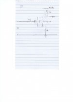
I have included 3 cct attachments:
#1 is the basic 1st stage for a MM phono stage. The 1K 'gain resistor' between the Drains of the 2SK170s and the +ve rail delivers about 40x gain.
So this has a heavy Miller capacitance load on the cartridge.
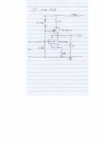
#2 has added a CCS between the Drains of the 2SK1I70s and the +ve rail. My understanding is that the CCS reduces distortion (compared to #1) - but keeps the same high level of Miller capacitance, right?
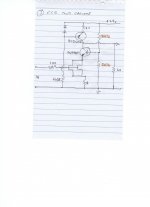
#3 has a 2n4401 as a cascode on the 2SK170s. (Have I drawn this correctly?)
So #3 is what needs to be used for the 1st stage of an MM phono stage, to avoid cap-loading the cart - right?
If that is so, can you advise what voltage the Base of the cascode transistor needs to sit at?
(I had assumed about half way between the +ve DC rail and Gnd - hence the value given to the orange-highlighted resistors.)
Thanks,
Andy
Attachments
#2 and #3 are not drawn properly. In order to ease the requirements for the supplemental current source, there should be a cascode for #2 and the current source should feed the drain of the gain transistor (emitter of the cascode) so that the current source is dumping into a relatively constant voltage. The load resistor should be referred to Vcc, not ground. Thie circuit starts to look like a folded cascode that's been unfolded. This is shown in the redrawn circuit on the left.
The circuit on the right shows a folded cascode with split supplies to accommodate the needs of the 2SK/LSK 170. The gate leakage on these transistors is such that it increases exponentially at a relatively low voltage .Running them at a Vds of 4-5 volts is a compromise between keeping the gate leakage to a relatively low value and having enough Vds to reduce the parasitic capacitance of the device. Splitting the supplies as shown in the circuit on the right allows running the input fet at a relatively low voltage, while allowing enough output signal swing for dynamic range and overdrive tolerance.
Other fets are not as restrictive as the @SK/LSK170 regarding drain voltage vs. gate leakage. A classic example id the PN4393, originally slated for switch/chopper duty, but also can be utilized a a fairly low noise amplifier.
Attachments
Thanks very much for the re-drawn versions of my #2, wrenchone. 
I'm not surprised #3 is drawn wrongly - that was my uneducated attempt to add a cascode to #2.
#2, however, is a real circuit - which actually sounds very good.
My fundamental reason for wanting to add a cascode was to zero-ise the Miller capacitance of this gain stage (otherwise, as you pointed out above, it makes it hard to correctly cap-load a MM cart if it is the 1st gain stage in a phono stage).
But it's nice to hear that it helps the CCS, too.
In your redrawn circuit on the left:
Q1. Q1 is the CCS transistor and Q2 is the cascode transister - right?
Q2. When you say "The load resistor should be referred to Vcc, not ground. " - I presume the "load resistor" is R5?
Thanks,
Andy
#2 and #3 are not drawn properly.
I'm not surprised #3 is drawn wrongly - that was my uneducated attempt to add a cascode to #2.
#2, however, is a real circuit - which actually sounds very good.
In order to ease the requirements for the supplemental current source, there should be a cascode for #2.
My fundamental reason for wanting to add a cascode was to zero-ise the Miller capacitance of this gain stage (otherwise, as you pointed out above, it makes it hard to correctly cap-load a MM cart if it is the 1st gain stage in a phono stage).
But it's nice to hear that it helps the CCS, too.
and the current source should feed the drain of the gain transistor (emitter of the cascode) so that the current source is dumping into a relatively constant voltage. The load resistor should be referred to Vcc, not ground. The circuit starts to look like a folded cascode that's been unfolded. This is shown in the redrawn circuit on the left.
In your redrawn circuit on the left:
Q1. Q1 is the CCS transistor and Q2 is the cascode transister - right?
Q2. When you say "The load resistor should be referred to Vcc, not ground. " - I presume the "load resistor" is R5?
Thanks,
Andy
R4 is the load resistor for the circuit on the left
Aah, thanks very much!
fyc, I've attached the drawing of your 2x cct alternatives:
Q1: so if I set R4 to 1K ... should I get a gain similar to what I did in my cct #1 (also attached fyc - ie. about 40x).
Q2: and R5 & R6 should be set so that the Base of Q2 is at about the 15v point? (Say, 3K3 each?)
Regards,
Andy

Here's a simulated output section, incorporating a hotly biased PN4391 for gain duty and an output source follower to drive difficult loads. Distortion is much lower than your typical Pacific common source output stage when driven to 1V output. Gain is about right at 33X. Paired with a 40X input stage, Gain will be ~40 dB at 1kHz, great for a MM cartridge.
Attachments
Last edited:
- Home
- Source & Line
- Analogue Source
- Ultrasimple MM/MC RIAA preamp 2