Hi good day. A consequence of Calvin's suggestion, I downloaded the LTspice simulator, and I began to play with it.
The simulations were three DIY phono stages, two of which are well known on the web. The third not so well known. I Built the P6 Rod Elliot; Solidphono TNT, missing me but so pretended VSPS.
I have simulated the frequency response and gain with sinusoidal generator at its entrance and a magnetic capsule simulator (made by Calvin), specifically the one I have (Audio Technica 440 MLA).
I would like you to analyze charts and I explain the large variations between the actual response to sinusoidal input and the linearity to do with the magnetic capsule.
If phono stages really react that way against different impedance and inductance magnetic capsules, I think not worth the effort to continue to perfection RIAA curve.
photos:
VSPS
Elliot
Solidphono
Regards.
 Removed 1st, 2nd, and 4th picture per Alpuy's request. (Hopefully got it right)
The simulations were three DIY phono stages, two of which are well known on the web. The third not so well known. I Built the P6 Rod Elliot; Solidphono TNT, missing me but so pretended VSPS.
I have simulated the frequency response and gain with sinusoidal generator at its entrance and a magnetic capsule simulator (made by Calvin), specifically the one I have (Audio Technica 440 MLA).
I would like you to analyze charts and I explain the large variations between the actual response to sinusoidal input and the linearity to do with the magnetic capsule.
If phono stages really react that way against different impedance and inductance magnetic capsules, I think not worth the effort to continue to perfection RIAA curve.
photos:
VSPS
Elliot
An externally hosted image should be here but it was not working when we last tested it.
Solidphono
An externally hosted image should be here but it was not working when we last tested it.
An externally hosted image should be here but it was not working when we last tested it.
Regards.
Removed 1st, 2nd, and 4th picture per Alpuy's request. (Hopefully got it right)
Last edited:
Apologies for grave error to simulate VSPS and Elliot AT 440MLa cartridge.
I forgot vee and VCC in operational amplifiers.
Now if:
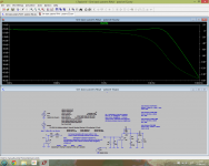
ELLIOT WITH AT 440MLa
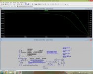
VSPS WITH AT 440MLa
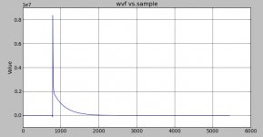
I'm surprised the fall of high frequencies in this simulation.
Apologies again. I'd like your input for errors in the simulation and if this were correct that comments would be about the RIAA response.
greetings
I forgot vee and VCC in operational amplifiers.
Now if:
ELLIOT WITH AT 440MLa
An externally hosted image should be here but it was not working when we last tested it.
VSPS WITH AT 440MLa
An externally hosted image should be here but it was not working when we last tested it.
I'm surprised the fall of high frequencies in this simulation.
Apologies again. I'd like your input for errors in the simulation and if this were correct that comments would be about the RIAA response.
greetings
Last edited:
<snip>
I'm surprised the fall of high frequencies in this simulation.
Apologies again. I'd like your input for errors in the simulation and if this were correct that comments would be about the RIAA response.
greetings
Mechanical resonances are not modeled which might account for part of the error? I can't see your circuit models clearly in your pictures so I can't tell if your cartridge electrical models are reasonable or not.
Hi,
unfortunately the pics are of too low quality to make trustworthy comments.
Still though some issues are noticeable.
- You could make screen copies with the print button of Your keyboard and paste them into a prog like photo paint, store and upload those pics. Much better quality and resolution.
- Do Yourself and us the favour and draw the schematics in a clear and clean way.
- use shorts for parts values like k, Meg, m and µ. 180k certainly reads easier than 180000.
- choose appropriate values for the sources. In Pic#1 that could be 5mV as equivalent for a typical MM-cartridge´s output voltage. You might have noticed that the value-script for part E1 I supplied contains the factor ´gain´. Gain tailors E1´s output voltage level to the required value.
Keep in mind that in the transient sim the source voltage is a peak-value while in the AC sim the voltage is the effective value (RMS). 5mVp in Tran equals 5mV/sqrt(2) in AC (~3.5mV).
jauu
Calvin
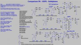
Hi,
just played around")
Parmeters Rpu, Lpu and Gain are chosen as to emulate a AT-440MLa pickup.
The Solidphono´s input gain stage is emulated by E4 with a gain of 100 (+40dB)
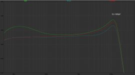
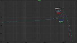
1st Plot shows the amplitude response of all three phonos with a capacitive load of 300pF (summed value of input capacitance, cabling etc.)
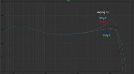
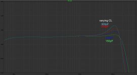
2nd to 4th plot show the respective phono´s output with varying load capacitance from 150pGF to 300pF.
As typical for rather low inductance/low resistance pickups like almost all AudioTechnicas they react very strongly on capacitive loading and require rather lowish CL values.
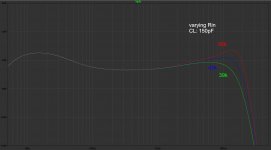
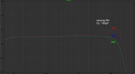
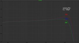
For AudioTechnicas I rather suggest to use the lowest possible load capacitance and trim the amplitude response by varying the 47k input loading resistor.
That conserves higher bandwidth and still allows to trim the HF-response.
This is shown in plot #5 to #7
jauu
Calvin
just played around
Parmeters Rpu, Lpu and Gain are chosen as to emulate a AT-440MLa pickup.
The Solidphono´s input gain stage is emulated by E4 with a gain of 100 (+40dB)
1st Plot shows the amplitude response of all three phonos with a capacitive load of 300pF (summed value of input capacitance, cabling etc.)
2nd to 4th plot show the respective phono´s output with varying load capacitance from 150pGF to 300pF.
As typical for rather low inductance/low resistance pickups like almost all AudioTechnicas they react very strongly on capacitive loading and require rather lowish CL values.
For AudioTechnicas I rather suggest to use the lowest possible load capacitance and trim the amplitude response by varying the 47k input loading resistor.
That conserves higher bandwidth and still allows to trim the HF-response.
This is shown in plot #5 to #7
jauu
Calvin
Attachments
-
 Comparison Phono Stages - P6 - VSPS - Solidphono.jpg316.8 KB · Views: 237
 -
 Comparison Phono Stages - P6 - VSPS - Solidphono - Amplitudes CL_300pF.jpg157.1 KB · Views: 220
 -
 Comparison Phono Stages - P6 - Amplitudes - var_CL 150-300pF.jpg156.1 KB · Views: 177
 -
 Comparison Phono Stages - VSPS - Amplitudes - var_CL 150-300pF.jpg155.2 KB · Views: 177
 -
 Comparison Phono Stages - Solidphono - Amplitudes - var_CL 150-300pF.jpg156.7 KB · Views: 171
 -
 Comparison Phono Stages - P6 - Amplitudes - var_Rin 39k-47k-56k.jpg156.9 KB · Views: 104
 -
 Comparison Phono Stages - VSPS - Amplitudes - var_Rin 39k-47k-56k.jpg151.5 KB · Views: 108
 -
 Comparison Phono Stages - Solidphono - Amplitudes - var_Rin 39k-47k-56k.jpg155 KB · Views: 119
Last edited:
I did a minimum phase RIAA (5440 coefficients @96K) for my article in the next Linear Audio, ~.00001dB and .00002 degree even at 20Hz without using any windowing.
Interesting!
Could you share the curves as txt files?
I plan to emulate the RIAA deemphasis using simple EQs.
It looks like 2 to 3 EQs are enough to get a +/-0.01dB result, which is enough for what I want to achieve (and probably more accurate than most of the analog preemphasis units), but I would like to check with some reliable data.
The magnitude curve only would be enough for this evaluation.
The advantage of having it integrated in rePhase would be to add further EQs and corrections (HP for remove rumble, speaker EQ, crossover phase linearization, etc.) without having to chain several corrections.
Hello Calvin. I tell you, I am a lover of good audio and good sound as well as the DIY hobbyist.
But I'm not technical or anything like that. I am self-taught in the subject. Only 35 years I'm building my audio equipment.
But actually I do because I like to take the stress and gives me my profession. It is that I am a doctor and my job after my hobby is music.
That's why I make mistakes in cosntruccion circuit and in this case newly esyoy learning to use the simulator. As I liked the game I started to simulate circuits phono has built and which are named more on the web.
I've been tempted to shop online phono stage as the Pro-ject or similar, but actually I will stay with my Solidphono which has me very happy. (Although I'm sure it would improve with a good design pcb)
Greetings and thanks for taking the job of simulating my three circuits and share with me.
I know I have a friend to turn to when you need.
PD: por lo que veo en los graficos, el preamplificador que mejor se comporta en cuanto a respuesta RIAA es el VSPS. Si ustedes me lo confirman, ya estoy comprando el kit.
Last edited:
The advantage of having it integrated in rePhase would be to add further EQs and corrections (HP for remove rumble, speaker EQ, crossover phase linearization, etc.) without having to chain several corrections.
Sure, but it only takes a minute to plot the magnitude of the three term complex RIAA vector in Octave or Python.
RIAAmag(f) = 20*log10(abs((1jf + 500.48724)/((1jf + 2122.0659)*(1jf + 50.048724))))
Picture below of the RIAA impulse response. I printed this to text normalized to 24 bits (2^23-1) if you want it. I found it difficult using standard design tools to get accuracy at 20Hz, the FFT of the impulse response of Audacity's RIAA effects was off .3dB at the low end even at max points. An artifact of the trick I used is a 4 usec uniform delay which I don't think matters.
Attachments
Last edited:
Thanks, now I see where the difference came from: my version had the additional 3.18uS (50kHz) time constant that changes the top end.
Yes, that should be a user selected option. I did both versions for each sampling frequency.
Hello. I'm bothering with the issue of RIAA response.
I've seen in my preamp simulator Solidphono (and others I've simulated), to simulate the pickup then presents the 12-13 khz about a fall of up to 4 dB amplitude to reach 20 khz.
Playing with the simulator and after several attempts has improved to - 1.45 dB adding a 1000pF capacitor in parallel with R1. (also an increase of + 0.52 dB at 13 kHz it is noted).
All this would be convenient or RIAA is best left flat response up to 13 kHz and accept porterior fall.
All this is for the purposes of empirically correct answer, because my age really get to hear only up to 13 khz and no more.
Regards.
Attachments
Hi,
keep in mind, that the simulation assumes a perfect pickup response.
It doesn´t account for mechanical resonances-related amplitude deviations.
Almost all pickups show a peaking rise in their HF-response which ´counters´ the drop in the electrical amplitude response to a large degree.
If You still think while listening that the upper bandwidth limit is too low with common 47k||xxpF loading, try with the lowest capacitive loading and -if necessary- vary the 47k-resistor instead.
Raise the resistance with slightly dark sounding pickups (Shure M97, 68k) and lower the value if the pickup sounds rather bright (AudioTechnica AT-440, 39k)
The RIAA response eventually drops down to 0 at HF.
Adding that cap bypasses the resistor and gives a HF-boost, but it also forms a capacitive voltage divider, hence it alters the original RIAAA response at HF in a way, not droppig to 0 any more.
That is similar to the output of a non-inverting, active feedback (or shunt feedback) stage that´s again levels out at a minimum of 1.
That´s the reason why one finds a passive RC-network at the output of such stages ..... to let the signal level drop to 0, so that the RIAA recommendation is followed pecisely.
jauu
Calvin
Last edited:
Calvin OK, thank you very much for your advice. I have just seen that there is a fall simulator amplitude from 13 khz and I happened to test with the addition of the capacitor. But always in the simulator.
I am very pleased with this phono stage. Really do not know if it's the design; or I have measured almost exactly the components of the RIAA network, but to be a DIY circuit made by a hobbyist like me, the sound is excellent. What is missing and I do not really like, is a good PCB design. I saw a Hungarian website selling it but I can not contact me.
Finally I wish someone contruirlo and be encouraged to share your opinion.
Regards.
RIAA accuracy
Hi,
If you go to page 34 "MEASURING RIAA ACCURACY" of AudioXpress magazine 2/2004
(http://waltjung.org/PDFs/GFP565_Pt4_Galo_AX_0204.pdf) you will find a method to measure RIAA accuracy by G. Galo.
Hi,
If you go to page 34 "MEASURING RIAA ACCURACY" of AudioXpress magazine 2/2004
(http://waltjung.org/PDFs/GFP565_Pt4_Galo_AX_0204.pdf) you will find a method to measure RIAA accuracy by G. Galo.
Last edited:
The easy way to check for correct RIAA response is to check that it is +20dB at 20Hz and -20dB at 20KHz, both referenced to 0dB at 1KHz. As long as your slopes are 6dB/octave, which they must be with any sane RIAA circuitry, and there are two of them joined by a straighter section, everything else follows.
In my experience inverse RIAA networks are even harder to build accurately than RIAA networks, and if you build it passively you either need to get +40dB of gain from somewhere or else inject about a 20V sine wave into it, because it has at least 40dB loss.
In my experience inverse RIAA networks are even harder to build accurately than RIAA networks, and if you build it passively you either need to get +40dB of gain from somewhere or else inject about a 20V sine wave into it, because it has at least 40dB loss.
Hi,
there are several suggestions for passive inverse RIAA networks .... I built mine ages ago roughly following Hagerman's suggested values .... and it is very precise and a very convinient tool ... either with -40dB attenuation @1kHz and ~600R O-impedance or -60dB and 60R.
Feeding 1Vrms from a signal generator results in 10mV, resp. 1mV @1kHz at the phono pre's input.
MMs are typically specced at 3-10mV, low output MCs around 0.15-0.5mV.
Feeding a passive Inv-RIAA with a 20V sine (+26dBV!!) would overload many Preamps.
jauu
Calvin
Page 52 0f the APT HOLMAN preamp manual contains an inverse RIAA circuit claimed to be accurate to within +- 0.1 dB .
http://www.amplimos.it/images/apt-holman-preamplifier-service-manual.pdf
http://www.amplimos.it/images/apt-holman-preamplifier-service-manual.pdf
iRIAA are not that hard. Except we expect them to be "perfect" references for measuring listening circuits.
At a super-simple level, you can steal the NFB network from a NFB RIAA preamp, turn it around, and it "is" an iRIAA network. This form will roll-off at or beyond the top of the audio band. And if the one you steal was hacked to complement the flaws of the amp it was wrapped around, you get unknown errors.
Any level head can compute RIAA or iRIAA.
It may not be wise for the same head, working alone, to compute both preamp RIAA and the iRIAA to test it. Make a related mistake twice and it won't be right even if it looks good. I always "steal", either complete or as a cross-check on my figuring.
There are several debatable points. The base RCA Orthophonic did not specify a 50Hz corner, but it clearly can not rise to infinity, and in those days 50Hz was as low as anybody wanted in their radio or phono loudspeakers, as shown by RCA's suggested implementations. The present "RIAA" explicitly calls for a 50Hz corner.
Later IEC proposed adding a 20Hz corner. Not a bad idea, but not enough, too late, and also not easily fit into the basic NFB topology. The trend is to either ignore it, or have an optional multi-pole ~~20Hz low-cut.
There was a rumor that Famous Brand record cutter had a 50KHz kink, and 50KHz rise was advocated. After all, recorded treble can not rise to infinity. But it was never a simple single 50KHz pole, not the same for all cutters, and the Cutting Engineer really decides what will get on the cut. And for most MM pickups, the top resonance will put 50KHz 12+dB down from "ideal". However the 3uS/50KHz bend is implemented in some iRIAA circuits, and you need to know because it skews your 20KHz gain.
Let's compile several well-known inverse RIAA networks and their simmed responses.
http://www.amplimos.it/images/apt-holman-preamplifier-service-manual.pdf
Spice and the art of preamplifier design, Part 1
iRIAA2 - Inverse RIAA Filter – Hagerman Audio Labs
Attachments
Last edited:
- Status
- This old topic is closed. If you want to reopen this topic, contact a moderator using the "Report Post" button.
- Home
- Source & Line
- Analogue Source
- RIAA Response question