OK. So we need to start afresh with basics.
Make sure all the parts are refitted back in place and then we can do some more voltage checks. When you have refitted the parts do the following.
We are going to test the output stage. This will help prove whether the fault is to the left (the output stage) or the right (the oscillator)
1/ Remove T5 and then measure the voltage on R9 as before. The voltage should be under 1 volt.
What we are doing here is seeing if the output stage can swing its output between the rails. With T5 removed, T3 is OFF. That means that T2 and T7 are ON (via R13 supplying base current to T2) and the resistor R9 is pulled to the 'negative' rail.
So with T5 removed and your black lead on C2 negative and red lead on R9 you should see very little voltage.
Capacitance of the c9 with the one leg removed is exactly 0.1nf as it should be.
It should be 100nf ! which is 0.1uf (microfarad)
Lets go through these points.
1/ You measured C9 as 0.1nf. It should be 100nf")
2/ The caps shouldn't show any resistance at all. They should read as open circuit which I think is what you are saying.
3/ The variable resistor is shown as 5k on the diagram. That means it must read 5k or lower depending on where it is set. You measure that with the power OFF. So what you are reading there doesn't look correct at all.
1/ You measured C9 as 0.1nf. It should be 100nf
2/ The caps shouldn't show any resistance at all. They should read as open circuit which I think is what you are saying.
3/ The variable resistor is shown as 5k on the diagram. That means it must read 5k or lower depending on where it is set. You measure that with the power OFF. So what you are reading there doesn't look correct at all.
Look please at the shema. Here is 100p near the C7.
Yes, C7 is 100pf on the diagram. 100pf is 0.1 nano farad.
C9 is 0.1 microfarad. That is 100 nano farad.
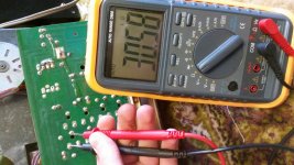
T5 removed. black lead on C2 negative and red lead on R9:.
First seconds it was 3.2V but then came some noise (zhzhhzzhhz) and the voltage rised to 32V. What is it?
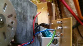
That doesn't sound good. Make sure the 0.3 ohms are still OK and that nothing looks burned. Did the noise come from the motor ? We might need to disconnect the motor to work on this.
0.3Ohm are good, nothing burned
Good.
5K is a pitch control and it shows me 3.13K
That sounds fine.
So with T5 removed there should not be this 32 volts on R9. Lets see where it goes wrong then.
Check these voltages and see what you have. Black lead on C2 negative and keep T5 removed.
Is it easy to disconnect the motor ? as that will remove doubt about the motor superimposing a voltage on what we are trying to measure.
T3 emitter should be supply voltage, what was that, 34 volts or so.
T3 base should be the same as the emitter.
T3 collector should be near zero.
T1 emitter should be near zero.
T1 base should be near zero.
T1 collector should be at positive supply (34v)
T2 emitter, base and collector should all be near zero.
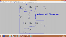
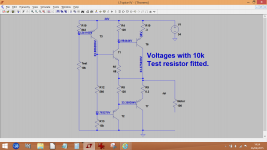
This shows the circuit redrawn to make it easier to follow. Its a working simulation of the output stage. The first shows the approximate voltages with T5 removed. The second shows the voltages with a 10 TEST RESISTOR fitted. This resistor turns the output stage on and changes all the voltages.
Compare the readings you get with those of the drawings. If you haven't got a 10k resistor then remove R19 (8k2) and fit that as the test resistor.
Compare the readings you get with those of the drawings. If you haven't got a 10k resistor then remove R19 (8k2) and fit that as the test resistor.
Attachments
- Status
- This old topic is closed. If you want to reopen this topic, contact a moderator using the "Report Post" button.
- Home
- Source & Line
- Analogue Source
- Thorens 125 MK1. Help me please repair this PCB.