Hello everyone!
I intend to make a correction RIAA preamp transistor for a friend but I would like to have your opinion on the following diagram.
I also have a question about the capacitor 250uF is it related to the RIAA is correct or that a 220uF capacitor is suitable?
The link to the original scheme is on the website of Paul Kemble (A Paul Kemble web page - John Linsley Hood preamp designs.).
Thank you!
Attachments
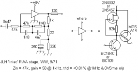
A while after the liniac, Linsley-Hood created the super-liniac, where the input bipolar was cascoded by a FET. The open loop gain was said to be very high.
The first circuit using the super-liniac was called "RIAA reference standard" by the author and had a CFP push pull output stage.
The second version has a single ended output stage, it was part of an integrated 2 * 30 W amplifier.
I built this second version, but with a 10 kOhm input for a Grado cartridge requiring this load, and suppressed the electrolytic cap which has not the AndrewT's agreement.
There was no annoying noise but it was very sensible to a RFI of an FM emitter which was about 100 m from where I lived.
I don't want to be a Negative Nancy but that design looks like it'll be quite noisy as you have a 47K resistance in series with the input which you are then amplifying by a considerable amount.
You'd probably do a lot better to use the two transistor non inverting amplifier topology for this. There are plenty of better circuits out there and you could build yourself something with fairly good performance with 3 transistors per channel.
You'd probably do a lot better to use the two transistor non inverting amplifier topology for this. There are plenty of better circuits out there and you could build yourself something with fairly good performance with 3 transistors per channel.
that design looks like it'll be quite noisy as you have a 47K resistance in series with the input which you are then amplifying by a considerable amount.
This JLH topology does have about 14dB worse s/n for a 47k load mm cartridge, although a head amp can mitigate this.
However, there are reasons of sound quality that this circuit remains well regarded.
Well you only have about 3 volts of headroom either way, or even less, so you can't boost the signal upstream or you'll end up with overload.
This just looks like an on-the-cheap type job that you'd find in low quality equipment in the early 80's.
If you want a good discrete phono preamp use a single supply of 24V and a 3 transistor non inverting topology. If you want to use a low supply voltage then use a rail to rail op-amp. But this circuit will have a very low signal to noise ratio when compared to other offerings.
This just looks like an on-the-cheap type job that you'd find in low quality equipment in the early 80's.
Not at all, it's a well known, highly regarded circuit by an expert from the BBC.
Here's something to look at/try:
http://www.diyaudio.com/forums/analogue-source/203999-jfet-mosfet-gain-cell.html
http://www.diyaudio.com/forums/analogue-source/203999-jfet-mosfet-gain-cell.html
Which expert? The distortion performance may be adequate but the headroom is pitiful
and the noise is a good 10dB higher than conventional offerings.
John Linsley Hood.
Too few or too many semiconductors don't make a good sounding amplifier.
Well you certainly reach a point of diminishing returns, most op-amps have about 30+ and many sound excellent.
When you're DIYing it doesn't make sense to do your design, electrical components and other fairly low cost parts on the cheap.
I think the link has not yet been given.
This is the initial Linsley-Hood's article
about his Liniac circuit :
http://www.keith-snook.info/wireles...rld-1971/The Liniac - John L Linsley Hood.pdf
This is the initial Linsley-Hood's article
about his Liniac circuit :
http://www.keith-snook.info/wireles...rld-1971/The Liniac - John L Linsley Hood.pdf
John Linsley Hood.
But he was not 'from the BBC'. He worked for a cellophane manufacturer.
Still a well known author and designer in his day on Wireless World.But he was not 'from the BBC'. He worked for a cellophane manufacturer.
The design had an unusal noise spectrum due to the series resistor. It gave high noise levels at low frequencies and less at higher, where the MM inductance became significant. This turned out to be subjectively pleasant.
The reason behind the shunt feedback, was that the gain at h.f. would go to zero, as the standard requires, rather than rolling-off to 1 as would happen with series feedback around a single gain stage.
I built a Liniac RIAA stage, based on series of JLH articles in HiFi News & Record Review in Feb. 1980.
The cartridge loading resistor was 39 kOhm, rather than 47 kOhms, which reduces the noise contribution by 1 dB. JLH also mentions in the article that the increased loading of the cartridge is supposed to help with playback of square-wave transients.
The stage in the article had a JFET cascode in addition to the circuitry mentioned earlier in this thread. The maximum output voltage of the stage is 6 Vrms - certainly less than a more modern op-amp based stage, powered from +/- 15 V would achieve.
There was a slight rustle to be heard when the record player was off-disc, but noise was significantly less than vinyl surface noise.
Can't really judge the sound quality - it was certainly better than the budget amplifier it replaced, although I had no experience or anything to compare to - and I'd built it, so I'm probably biased...
- Home
- Source & Line
- Analogue Source
- JLH "Liniac" RIAA