Hi everybody!
I would like to build the fvp5a phono stage as a stand alone phono preamp to be then coupled with a existing line preamp.
I have two questions about the schematics that I have found on vacuum state's website (Schematics).
First I don't understand what should the capacitor bypassing the resistor (6k8) on the first tube's grid be. It is signed as 25/25. What does it mean?
Second on the project it says that the gain control must have an exact and stable 50k impedance. Since I don't know which is the entry impedance on the line preamp and I would like to make it somehow "plug&play" I thought I could add a 50k resistor in parallel with the 1M resistor and then a capacitor in series with the output signal pathway (after the 50k resistor). Is it a good idea? I hope I have made myself clear.
Member
Joined 2009
Paid Member
if the design needs to see a constant 50k load (?) then it means not just DC but also across the audio range. if you choose the circuit with a cathode follower at the output it will not be so sensitive to the load. The link you provided shows some schematics with cathode follower output.
This may also be of interest to you: https://darklanternforowen.wordpress.com/2014/08/23/phono-stage-diego-nardi-φ42/
http://mmiworks.net/sprc/SP14-Nardi.pdf
This may also be of interest to you: https://darklanternforowen.wordpress.com/2014/08/23/phono-stage-diego-nardi-φ42/
http://mmiworks.net/sprc/SP14-Nardi.pdf
Last edited:
Thank you for your help!
On the schematics there are both the phono circuit with an anode output and subsequently the line circuit with the cathode follower output. I would like to build just the first part since I already have a line preamp. The designer says that there needs to be a stable 50k load so that there are no changes in the riaa equalization. Because of this I thought that adding a 50k resistor and then a coupling cap may help. Thank you for the design you posted! It looks very nice but I would like to build a mc phono stage without the need for a step up transformer.
On the schematics there are both the phono circuit with an anode output and subsequently the line circuit with the cathode follower output. I would like to build just the first part since I already have a line preamp. The designer says that there needs to be a stable 50k load so that there are no changes in the riaa equalization. Because of this I thought that adding a 50k resistor and then a coupling cap may help. Thank you for the design you posted! It looks very nice but I would like to build a mc phono stage without the need for a step up transformer.
I would like to build just the first part since I already have a line preamp. The designer says that there needs to be a stable 50k load
so that there are no changes in the riaa equalization. Because of this I thought that adding a 50k resistor and then a coupling cap may help.
The 50k load spec (for EACH of the balanced sides) is for the total loading, and includes your line amp. This is critical for accurate RIAA.
This loading must be AFTER the two coupling capacitors however, like the volume controls in the original circuit
Last edited:
Ok thank you! So how could I solve this problem? For example in my line pre I have a stepped attenuator which can change a bit the load.
Assuming your preamp is balanced, you could use different (50k) attenuators. Or, use a buffer circuit after the dual 50k loading. What's the circuit for your line amp?
You may be able to use a pair of directly coupled cathode followers from the phono circuit (with the 100k RIAA loading between the grids), and the coupling capacitors at their outputs.
Last edited:
It is a clone of a Kondo M77 (Kondo - Audio Note M7 Tube Pre-amp Clone | DMS Audio)
It is a clone of a Kondo M77 (Kondo - Audio Note M7 Tube Pre-amp Clone | DMS Audio)
Ok, that's a straightforward circuit. Is your version a balanced or single ended line amp? The phono stage is balanced.
Last edited:
I haven't read the replies carefully. The reference to the 50K being exact at any volume level is because it affects ( is part of !) the RIAA equalisation. You will notice that there is no 1meg grid to ground resistor. So a 50 K volume pot will look like 50K at any volume position. If you add the usual 1 meg at the grid, it will NOT be 50 K at all positions.
While you could use a switched 50K volume switch, the wiper must be MBB ( make before break ) type. Otherwise you will get a bang each time you switch the volume. This is IF you do not use a 1 Meg resistor at the grid. But as mentioned before you cannot use a grid to ground resistor.
Alternate method is to just use a cathode follower with a 50K input impedance and then follow up with a stage with gain. You will have a slight noise penalty here. But possibly not of much consequence.
Thank you everybody for your replies! my line preamp is unbalanced and this should be true also for the fvp5a (the rtp3c is balanced- Am I right on this?). I'm sorry if I ask again but it is not clear to me.(excuse me, I am only a beginner). I imagined that putting a capacitor after the volume pot and before the grid of the next tube would "isolate" the first part of the circuit and make it independent of the next input load. And if this is true instead of a volume pot I could use a simpler 50k resistor. Thanks again
Member
Joined 2009
Paid Member
A coupling capacitor provides DC isolation only, for AC (the signal) this capacitor will have an impedance that varies with frequency and so will not provide load isolation at audio frequencies unless it is very small - and then your signal won't be coupled to the next stage. Usually the capacitor is made large enough not to get in the way of the signal and hence can't isolate the output from the load. What you need is a buffer, a circuit with high input impedance and low output impedance. A Cathode Follower can do this when designed right. A MOSFET source follower may be better under many circumstances.
Member
Joined 2009
Paid Member
With a high impedance buffer you can 'load' the output (before the cathode follower) with a resistor of around 50k and this will provide that ideal load the circuit seeks. In reality the cathode follower has a finite and potentially non-linear input impedance but this may be of no consequence in practice.
It is often recommended that the best choice of tube for a cathode follower has high transconductance. I've seen people use 6DJ8 for example. There are more extreme options such as 6c45p.
It is often recommended that the best choice of tube for a cathode follower has high transconductance. I've seen people use 6DJ8 for example. There are more extreme options such as 6c45p.
Last edited:
Ok thanks! Everything is more clear now! Thank you for the explanation! I think I will try to add a cathode follower and see how it goes!
If you have a single-ended line amp, the balanced phono circuit may not be what you want. Using only one output side of the circuit
loses the advantage of noise rejection, but it still has twice the components of a standard circuit.
Do you understand that this balanced phono circuit is only for one channel? You need two of these circuits for stereo.
The cartridge coil of one channel is floated across the two inputs, which is a differential input, and so this results in a differential output.
You would need two copies of the circuit for two differential channels.
Last edited:
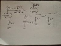
I have finally been able to upload the schematics!
The 50k volume control is a very critical part of this RIAA circuit. With a cathode follower however, instead of a 50k to ground, you can replace
the series 32.4k resistor by a value equal to the parallel combination of 50k and 32.4k (or just parallel the 32.5k with a 50k).
Then, insert the cathode follower just before the 1uF coupling capacitor, directly coupled to the final RIAA circuit.
You would also need a cathode resistor to ground for the cathode follower, before the 1uF cap..
Last edited:
Thank you! Something like this if I have understood correctly.
Yes, this should work. Any added capacitance from the cathode follower should be very small, and will not change the curve..
- Status
- This old topic is closed. If you want to reopen this topic, contact a moderator using the "Report Post" button.
- Home
- Source & Line
- Analogue Source
- phono FVP5A