Hi there!
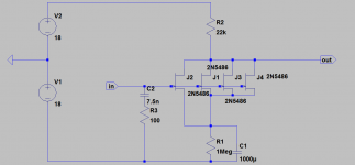
Here is an LTspice schematic of my proposed first stage. I am concerned about noise with MC cartridges....
LT spice does not seem to lower the noise figure when more jfets are added to the first stage, and the noise seems rather high, at around 110 uV. Using an op amp with feedback results in much much lower noise ( 1.6 uV ).
Is this solely due to the feedback? Can I acheive op amp levels of noise with jfets?
Thanks for your help!
Cheers!
Attachments

Can LTspice make pdf files? Here is a png via paint. I'm sure there is much wrong with this. It is my first ever circuit design. BTW: LTspice noise analysis does show a drop off in noise as the jfets were added. I was using it wrong...
Attachments
Last edited:
Hi,
attached is a changed file.
If the filter in the frontend should work at all it requires a series impedance it can work upon.
In the file the signal voltage sources therefore got a series resistance value of 1R.
Set it back to 0 and see the difference (for 75 choose appropriate values).
Then, the dimensioning of the circuit is completely off.
- The JFETs are almost fully cut off.
- The negative supply is not necessary, thanks to JFETs beeing depletion mode (normally on) devices and as long as the input voltage remains lower than the Vgs value.
- The Source resistor directly affects noise. The larger the more noise. So keep Rs as small as possible.
- The Drain resistor also affects noise- just on a smaller scale than Rs. Try to keep it as small as possible also. This requires to run the JFETs with considerable drain current.
- Choose rather high drain current values. Besides lowering voltage noise JFETs improve sonically when running a bit hot.
In the modded file the single-supply, lowohmic , high-Bias version´s noise figure is 16dB lower.
jauu
Calvin
Attachments
Last edited:
Wow! That is much more than I expected THANK YOU!
I was not sure how to set the values of Rsand Rd...
By saying that the jfets were nearly cut off, that means they were not working in saturation mode? Sorry for the newbie question, it's a little difficult picking this up just with googled info.
This site is invaluable for gems such as this!
Cheers!
You might get some ideas from Mike Renardson's preamp. He has the 75 us time constant in the first stage.
Phono Pre-amp Circuit
Phono Pre-amp Circuit
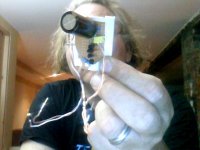
So here is a quick photo of the front end. Please excuse the use of the webcam. This shows the new connection strategy.... sip pins into the op amp IC socket.... V+, Gnd, In-, out.
This will be tested shortly.
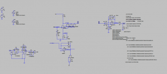
Attached is an ASC of the circuit, and png.... power supply not included....
The circuit on the lower left is the riaa equalization we are trying to undo...
This will be tested shortly.
Attached is an ASC of the circuit, and png.... power supply not included....
The circuit on the lower left is the riaa equalization we are trying to undo...
Attachments
Another probem... the yin-yang diode pair and parallel resistor cannot go between power supply common and earth. Since all signal grounds have been referred to PS common, this puts an odd impedance on the signal grounds of any ampifying section, which alters the RIAA equalization on actively equalized systems very bady.
- Status
- This old topic is closed. If you want to reopen this topic, contact a moderator using the "Report Post" button.
- Home
- Source & Line
- Analogue Source
- RIAA 75uS on first stage