Hello to all!
I have been reading the posts about low cost phono preamps,
and thought that it might be interesting to post a picture of my
variation on the El Cheapo phono preamp. It is a variation with
MM only, and uses regulated AC power supplies (I like very long
warm-ups for listening). It has the following features:
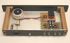
1. 4.2 Amp toroidal transformer
2. rectification bridge with Harris superfast/soft recovery diodes
with capacitor snubbers
3. 4700 uF Panasonic HFQ electrolytics with 2.2/.01 bypasses
4. JRC +/- 12 VDC regulators (1.5A) with very low noise levels
5. bleeder resistors on regulator outputs to bias regulators
to a higher current output level
6. 3 paralleled Black Gate 100uF electrolytics on regulator
outputs, plus poly bypasses at chip pins
7. Class A output bias on OPA 637 units
8. outputs are direct coupled to RCA jacks (no problems here)
9. all circuit board connections hard-wired point to point
10. seperated ground returns where possible
11. all aluminum case with hardwood end panels
I spent just $ 115.00 (with help from my junk box) to build this
preamp. Even though the transformer is just 6.5" from the
active circuit board, the hum level is inauduible from my own
listening position (I have a subwoofer) at -73dB relative to
a 0dB level on a vinyl record. I broke in the piece for 300 hours
and did 2-3 day warmups for listening. In my opinion, the sound
quality from this design (even without the battery power supply)
is simply stunning for the money. Very fine transparancy, sound
staging, resolution, and a fairly neutral overall sound that does
not at all seem very "solid state". Perhaps just a bit dark in
nature. I have listened to preamps costing much, much more
that did not do as well. Many thanks to Thorsten for his RIAA
network design for this circuit!
Fastcat
I have been reading the posts about low cost phono preamps,
and thought that it might be interesting to post a picture of my
variation on the El Cheapo phono preamp. It is a variation with
MM only, and uses regulated AC power supplies (I like very long
warm-ups for listening). It has the following features:
1. 4.2 Amp toroidal transformer
2. rectification bridge with Harris superfast/soft recovery diodes
with capacitor snubbers
3. 4700 uF Panasonic HFQ electrolytics with 2.2/.01 bypasses
4. JRC +/- 12 VDC regulators (1.5A) with very low noise levels
5. bleeder resistors on regulator outputs to bias regulators
to a higher current output level
6. 3 paralleled Black Gate 100uF electrolytics on regulator
outputs, plus poly bypasses at chip pins
7. Class A output bias on OPA 637 units
8. outputs are direct coupled to RCA jacks (no problems here)
9. all circuit board connections hard-wired point to point
10. seperated ground returns where possible
11. all aluminum case with hardwood end panels
I spent just $ 115.00 (with help from my junk box) to build this
preamp. Even though the transformer is just 6.5" from the
active circuit board, the hum level is inauduible from my own
listening position (I have a subwoofer) at -73dB relative to
a 0dB level on a vinyl record. I broke in the piece for 300 hours
and did 2-3 day warmups for listening. In my opinion, the sound
quality from this design (even without the battery power supply)
is simply stunning for the money. Very fine transparancy, sound
staging, resolution, and a fairly neutral overall sound that does
not at all seem very "solid state". Perhaps just a bit dark in
nature. I have listened to preamps costing much, much more
that did not do as well. Many thanks to Thorsten for his RIAA
network design for this circuit!
Fastcat
Attachments
To All:
The case for this preamp took more time than building the
active circuitry. The front and rear panels are milled from 1/4"
aluminum that were sandblasted & painted. I also did hand
lettering with white Press Type Letters, and overcoated the
panels with Krylon matt spray for protection. the hardwood
end panels are indeed 1 piece millings. This case took so
much time that I may never do this again!
As to the transformer inside the case, there is a residual hum
that is about 73 dB below what would be considered a 0 dB
level (about 4 mV signal @ 1 KHz) on a record. I suspect that having the transformer a bit farther away (mine was within 6.5") from the active circuit board would help with the 60 Hz hum, although I never heard any interference from it unless I was
up very close to my subwoofer.
I am curious if anyone has built this design and listened to it with a very high end turntable/cartridge combo to evaluate the sonics.
I use a Shure V15 series cartridge with a modified Dual belt drive
turntable.
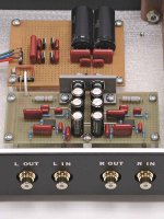
I have attached a detail shot of the circuitry.
fastcat
The case for this preamp took more time than building the
active circuitry. The front and rear panels are milled from 1/4"
aluminum that were sandblasted & painted. I also did hand
lettering with white Press Type Letters, and overcoated the
panels with Krylon matt spray for protection. the hardwood
end panels are indeed 1 piece millings. This case took so
much time that I may never do this again!
As to the transformer inside the case, there is a residual hum
that is about 73 dB below what would be considered a 0 dB
level (about 4 mV signal @ 1 KHz) on a record. I suspect that having the transformer a bit farther away (mine was within 6.5") from the active circuit board would help with the 60 Hz hum, although I never heard any interference from it unless I was
up very close to my subwoofer.
I am curious if anyone has built this design and listened to it with a very high end turntable/cartridge combo to evaluate the sonics.
I use a Shure V15 series cartridge with a modified Dual belt drive
turntable.
I have attached a detail shot of the circuitry.
fastcat
Attachments


NICE !!!!
Very nice work fastcat......
I also finished an El cheapo based phono pre recently(MM only). It`s been playing for a few days only, so I think it needs more time to "burn in" Compared to some other riias I have tried (Rega, NAD pp1 and an other diy riia) it sounds very promising. I find it very detailed, dynamic and it has a very good (3D) sounstage. May be bit bright/"over-analytical" with some recordings, but this might have nothing to do with the design (bad recording/record etc.). I use an alkaline battery powersupply so there is very little noise/hum.
I also switched cartridge after finishing the riia. At first I used an ortfon OM 10 (MM), then I mounted a Clear Audio Aurum beta and there was a clearly audile difference between the two cartridges (also in price). Better "everything", more dynamics, controlled bass and sibliance is very reduced with the new cartridge. The new cartridge also need some more groovetime so there might be more good sound heading my way....
My turntable is a Project 2 (not high end), but I must say I`am quite suprised that the new phono pre and cartridge make such a big positve difference.
HAPPY DIY
Very nice work fastcat......
I also finished an El cheapo based phono pre recently(MM only). It`s been playing for a few days only, so I think it needs more time to "burn in"
Compared to some other riias I have tried (Rega, NAD pp1 and an other diy riia) it sounds very promising. I find it very detailed, dynamic and it has a very good (3D) sounstage. May be bit bright/"over-analytical" with some recordings, but this might have nothing to do with the design (bad recording/record etc.). I use an alkaline battery powersupply so there is very little noise/hum.I also switched cartridge after finishing the riia. At first I used an ortfon OM 10 (MM), then I mounted a Clear Audio Aurum beta and there was a clearly audile difference between the two cartridges (also in price). Better "everything", more dynamics, controlled bass and sibliance is very reduced with the new cartridge. The new cartridge also need some more groovetime so there might be more good sound heading my way....
My turntable is a Project 2 (not high end), but I must say I`am quite suprised that the new phono pre and cartridge make such a big positve difference.
HAPPY DIY
fastcat95 said:Hello!
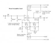
I have attached the schematic to this post.
Fastcat
Is this really the "el cheapo"? I have another scheme, and the bias resistor is 100k, and some caps for the DC on the output!
Raka:
You are right in seeing changes between my
version and the "El Cheapo".
My version has NO output capacitors, since
the component after the preamp has them.
I was trying to eliminate as much circuitry as
possible for best sonics.
There have also been changes to the input
resistor configuration, although the final out-
come is still around 50K ohm input impedance
for a MM cartridge.
The RIAA network is still the same as the origonal
"El Cheapo", although I obviously went to an AC
derived supply, rather than the batteries.
Have you built an "El Cheapo"?
Fastcat
I'm building it right now, one channel is finished. I also am not using batteries, it's for a simple preamp and space is a limitation.
One funny thing that i see is that it takes a LOT of time for the circuit to settle down to 0VDC output, I suppose this is for the caps to charge and with a very low time constant. No time to test it sonically.
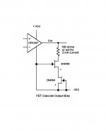
What about the cascode FET, any drawing?
Kuei, if you are listening, I know mine is not your configuration and can't expect the same results, but it's a pre for a friend and he doesn't want batteries. BTW, thanks for your circuit.
One funny thing that i see is that it takes a LOT of time for the circuit to settle down to 0VDC output, I suppose this is for the caps to charge and with a very low time constant. No time to test it sonically.
What about the cascode FET, any drawing?
Kuei, if you are listening, I know mine is not your configuration and can't expect the same results, but it's a pre for a friend and he doesn't want batteries. BTW, thanks for your circuit.
fastcat95 said:Hello!
I have attached the schematic to this post.
Fastcat
My preamp does not have a capacitor in entry.
Can I add MKP SOLEN 1µF + 100K to the ground at the ouput of this riaa ?
THX
fastcat95 said:Hello!
I have attached the schematic to this post.
Fastcat
Hi,
I am trying your schematic with P2P but I can not seem to get a good clean logical layout when soldering the parts on the bare pcb board. It seems the power supply wires will have to cross the small signal wires no matter which way I arranged the parts.
Do you mind sharing your actual layout / routing ?
The Butcher
- Status
- This old topic is closed. If you want to reopen this topic, contact a moderator using the "Report Post" button.
- Home
- Source & Line
- Analogue Source
- Check Out MY El Cheapo Phono Preamp!