")
@pcb121055,
Sorry, but it will take some time.
The housing of the cartridge is not the problem (see drawing and photo). It is small, but it can be done.
To get a very rigid symmetrical cantilever is more difficult. The tubes are very small (see photograph) and the total weight is about 50 milligram. I am afraid I have to make some “tools” to align the tubes before I try a new attempt to glue the tubes – one by one – together.
The weight of 50 milligram is nice because that’s comparable with a normal MC cantilever of 0,002.5 gram. The factor 20 is because a normal MC cartridge detects the modulation near the pivot of the cantilever. Detecting the modulation of the groove near the stylus will increase the sensibility of the cartridge about 20 times.
Nevertheless, a high end cartridge – like the Ortofon Anna – can probably detect the modulation of the groove with an accuracy of 98%. And the channel separation of the Ortofon Anna is between 22 and 25dB (that’s near the maximum audible detection of channel separation by human ears because of the reflections of the frequencies inside the room).
Therefore, what will we hear when all the expected “enhancements” of this new type of phono cartridge will function properly? Probably only “the sound” of an expensive cartridge. I expect no “magic cartridge”.
The biggest profit is probably a very low VTF (perhaps 1 gram, so there is little wear of the groove). Nevertheless, when I finished the first prototype of the tonearm, I didn't expect to hear much difference in comparison to an expensive fixed pivot tonearm. Fortunately I was wrong.
Sorry, but it will take some time.
The housing of the cartridge is not the problem (see drawing and photo). It is small, but it can be done.
An externally hosted image should be here but it was not working when we last tested it.
To get a very rigid symmetrical cantilever is more difficult. The tubes are very small (see photograph) and the total weight is about 50 milligram. I am afraid I have to make some “tools” to align the tubes before I try a new attempt to glue the tubes – one by one – together.
An externally hosted image should be here but it was not working when we last tested it.
The weight of 50 milligram is nice because that’s comparable with a normal MC cantilever of 0,002.5 gram. The factor 20 is because a normal MC cartridge detects the modulation near the pivot of the cantilever. Detecting the modulation of the groove near the stylus will increase the sensibility of the cartridge about 20 times.
An externally hosted image should be here but it was not working when we last tested it.
Nevertheless, a high end cartridge – like the Ortofon Anna – can probably detect the modulation of the groove with an accuracy of 98%. And the channel separation of the Ortofon Anna is between 22 and 25dB (that’s near the maximum audible detection of channel separation by human ears because of the reflections of the frequencies inside the room).
Therefore, what will we hear when all the expected “enhancements” of this new type of phono cartridge will function properly? Probably only “the sound” of an expensive cartridge. I expect no “magic cartridge”.
The biggest profit is probably a very low VTF (perhaps 1 gram, so there is little wear of the groove). Nevertheless, when I finished the first prototype of the tonearm, I didn't expect to hear much difference in comparison to an expensive fixed pivot tonearm. Fortunately I was wrong.
@thirdman,
You can use every existing turntable. Nevertheless, the centreline of the horizontal bar, the centre of the sphere and the surface of the record must be at exactly the same height. Probably you have to adapt the height of the existing platter.
If you don’t like the open sphere of the tonearm, you can attach a closed one in every colour you like (metallic, black, yellow: just order). You like a silver plated tonearm? Carbon is a conductor so you can cover everything with a thin layer (there are sites at the internet which will instruct step by step how to do it).
I have tried to “enhance” low-cost turntable parts to get a high end turntable (although these parts are over-prized too). Nevertheless, will you hear any difference between different kinds of moderate turntables (the noise of the motor and the noise of the bearing of the platter)? The biggest drawback is the fixed pivot tonearm. The substitution of the tonearm by this floating one and the damping of the shelf of the turntable is the most effective solution to improve the quality of the sound of vinyl records.
When it is late at night and there is no traffic, there is some profit from a turntable motor that’s totally quiet. But when there is always a bit noise from outside and you like bustling music too, why should you put any effort in getting “the ultimate turntable”? For example, a direct drive Technics turntable is just perfect!
Nevertheless, when you want "something special", you have to describe what is in your mind. Maybe I can try to make some drawings to realize "your wifes aesthetic dreams".
Back at home again (holiday) I started to listen to a record. But halfway the groove I noticed the tonearm was a bit too slow.
I changed the settings of the RCA connectors, but it didn’t result in a better operation. Anyway, I controlled the roller bar, but nothing was wrong.
So I decided to clean the bowl. And now I saw there was an invisible “layer” upon the water. Even the sphere had a rim of deposit at the waterline.
So I cleaned everything painstaking and filled the bowl with water again. Fortunately, everything was operating flawlessly like before.
I have put a bit vinegar inside the water too. Because the invisible layer of moisture must be something organic. Maybe this will prevent the growing of the moisture around the sphere.

@tomatamot,
That’s a real good advise! I’ll will try it immediately!
Anyway, the disruption of the proper operation of the tonearm by some moisture shows the fragile balance of the forces that are responsible for the correct trajectory of the sphere. Anyone who had the idea to try M5 silicon oil will now understand that this is in vain.
So it is not only the resistance against deforming of the tonearm wiring that can be a problem, but the pollution of the water inside the bowl can influence the proper operation too. Nevertheless, within some weeks I will untwist the tonearm wiring from the end of the armtube to the RCA connectors. Just to decrease the resistance (so it will become a “waterfall” of 80 threads, each 0,05 mm thick).
Some remarks about the cartridge
The image below shows the cantilever. It weights nearly 90 mg (without stylus) and the horizontal width to the pivot is 26 mm, the width between the centre lines of the magnets is 14,75 mm.
First of all, it is a hard job to make this cantilever. A stupid example: the moment I glued the magnets with epoxy I took the first one with the tweezers to put it on the epoxy on top of the carbon tube. But tweezers are mostly made from iron, so I couldn’t get the magnet free... This kind of silly mistakes will happen many times. Just because everything is really, really small.
I have stuck 2 magnets with double sided tape to the housing of the cartridge. So I could attach the cantilever to the pivot. I expected that the cantilever should “drift” upon both magnets (the housing was upside down at the table). Unfortunately, this didn’t work out the way I expected/hoped. The cantilever “flipped” to one of the magnets because they attracted each other side by side.
What is the problem... (see the right figure on the image below).
When the mutual distance of both magnets at one channel is to large, the cantilever can pass besides the magnets of the housing. The solution seems to be to attach both magnets of the housing a bit closer to each other... Unfortunately, this will influence the amount of VTF.
We all want a very low VTF because there will be less wear of the groove and the stylus. Manufacturers of high end cartridges advise a lifetime of the stylus tip of about 2000 hours (mostly cartridges with a VTF between 2 and 2,5 gram). Therefore, a VTF of about 1 gram is really nice! Very low friction between groove and stylus and – because of that – a far better steady rotational speed of light weighted platters (never thought about that?).
When I use a ring magnet instead of a disk magnet, the disk magnet of the cantilever will “fit” a bit into the magnetic “hole” of the ring magnet, attached to the housing of the cartridge. But when I bought all the magnets some month ago I could not find a suitable ring magnet (the inner diameter is too small and the magnet is to thick). See here.
Anyway, now I have ordered these ring magnets and some larger disk magnets (1 mm thick) to give it a try.
That’s a real good advise! I’ll will try it immediately!
Anyway, the disruption of the proper operation of the tonearm by some moisture shows the fragile balance of the forces that are responsible for the correct trajectory of the sphere. Anyone who had the idea to try M5 silicon oil will now understand that this is in vain.
So it is not only the resistance against deforming of the tonearm wiring that can be a problem, but the pollution of the water inside the bowl can influence the proper operation too. Nevertheless, within some weeks I will untwist the tonearm wiring from the end of the armtube to the RCA connectors. Just to decrease the resistance (so it will become a “waterfall” of 80 threads, each 0,05 mm thick).
Some remarks about the cartridge
The image below shows the cantilever. It weights nearly 90 mg (without stylus) and the horizontal width to the pivot is 26 mm, the width between the centre lines of the magnets is 14,75 mm.
First of all, it is a hard job to make this cantilever. A stupid example: the moment I glued the magnets with epoxy I took the first one with the tweezers to put it on the epoxy on top of the carbon tube. But tweezers are mostly made from iron, so I couldn’t get the magnet free... This kind of silly mistakes will happen many times. Just because everything is really, really small.
An externally hosted image should be here but it was not working when we last tested it.
I have stuck 2 magnets with double sided tape to the housing of the cartridge. So I could attach the cantilever to the pivot. I expected that the cantilever should “drift” upon both magnets (the housing was upside down at the table). Unfortunately, this didn’t work out the way I expected/hoped. The cantilever “flipped” to one of the magnets because they attracted each other side by side.
What is the problem... (see the right figure on the image below).
An externally hosted image should be here but it was not working when we last tested it.
When the mutual distance of both magnets at one channel is to large, the cantilever can pass besides the magnets of the housing. The solution seems to be to attach both magnets of the housing a bit closer to each other... Unfortunately, this will influence the amount of VTF.
We all want a very low VTF because there will be less wear of the groove and the stylus. Manufacturers of high end cartridges advise a lifetime of the stylus tip of about 2000 hours (mostly cartridges with a VTF between 2 and 2,5 gram). Therefore, a VTF of about 1 gram is really nice! Very low friction between groove and stylus and – because of that – a far better steady rotational speed of light weighted platters (never thought about that?).
When I use a ring magnet instead of a disk magnet, the disk magnet of the cantilever will “fit” a bit into the magnetic “hole” of the ring magnet, attached to the housing of the cartridge. But when I bought all the magnets some month ago I could not find a suitable ring magnet (the inner diameter is too small and the magnet is to thick). See here.
Anyway, now I have ordered these ring magnets and some larger disk magnets (1 mm thick) to give it a try.
I have tested the stability of the repulsive force of the neodymium magnets (1,5 x 0,5 mm) – attached at the cantilever and the housing of the cartridge – one more time. Now I have decreased the distance between the magnets of every channel a bit and have lined up everything as accurate as possible (within 0,02 mm).
Result: it works!
Nevertheless, this needs an accuracy that’s not easy to realize as a DIY project. So I hope that the ordered magnets with a larger diameter will make it possible to be a bit less accurate. I have ordered 3 mm, 4 mm, 5 mm and 6 mm disk magnets. All of them 1 mm thick (and ring magnets 6 x 2 x 2 mm).
Neodymium is not a very strong material. Therefore they have covered every magnet with a very thin layer of nickel. Perhaps it is possible to grind/polish them so the thickness will decrease (from 1 mm to 0,5 mm). As a result, the strong magnetic force of those larger disk magnets will decrease too (50%).
@MiiB,
I understand your doubt about the mass of the cantilever construction, because all the firm-made cartridges have as less mass as possible. The reason they choose minimal mass is the attachment of the damper close to the pivot of the cantilever. Because the VTF is responsible for the contact between groove and stylus tip and the damping is responsible for controlling the movements of the cantilever.
Controlling the movements of the tip of the stylus is not easy when the point of control is near the pivot of the cantilever. That’s why we grip a ball-pen near the point of the roller ball and not near the push button when we write.
The movements of the tip of the stylus inside the groove doesn’t change. With other words, when we want to decrease the forces to control the movements of the stylus, we have to decrease the mass of the cantilever + stylus. Anyway, when we control the movements of the stylus near the stylus itself, we can increase the mass in relation to the mass of the cantilever + stylus of a traditional MC cartridge.
Now it is easy to calculate the relation between the amount of mass we can “handle” when we control the movements of the stylus near the stylus itself. The difference is the distance between the rubber damper/repulsive magnetic force and the pivot of the cantilever. The length of the average cantilever of a traditional MC cartridge is about 10 mm. The rubber damper fits at the cantilever about 0,5 mm away from the pivot. Moving the rubber damper in the direction of the stylus will decrease the force 50% for every 0,5 mm. Conclusion: we can increase the mass of the cantilever about 20 times to met the specifications of an MC cartridge.
The weight of the cantilever + stylus of a traditional MC cartridge is about 5 mg, so the construction of the new cantilever + stylus can weight about 100 mg. The image in the post before shows a new cantilever that weights about 90 mg.
Fortunately, the design of the new cantilever has more profits.
First of all, the length of the cantilever is 2,6 x the length of the traditional MC cantilever. So the force that tries to move the stylus to the centreline of the groove is decreased by a factor of 2,6 (see image below). As a result, the stylus will keep a better contact at the top of the amplitudes at both walls of the groove (especially the higher frequencies).
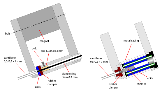
The new cantilever has a real pivot and is not a locked by a thin piano string (see the first image, left figure). Therefore, every change of the direction of the cantilever is totally free. Only the stylus is damped by the repulsive magnetic forces of the neodymium magnets. Moreover, the damping of both channels is not the result of a single rubber damper (image below), but is the result of 2 repulsive magnetic forces, each linear to the direction of the movement of the stylus by the modulation of each channel.
With other words: the damping of the inwards and outwards movements of the stylus is balanced, even when the amplitude of one channel is at the half of the groove of the other channel (!!!). A rubber damper never can adept to these asymmetric situations.
Nevertheless, the force that tries to move the stylus to the centreline of the groove still exist. Ideally, this force is a bit equal to the outwards forces of the moving inert mass of the cantilever + stylus. Because when it is possible to closely met this situation, we really can lower the VTF a lot (may be 0,5 gram will be enough). Just because the stylus will keep track in a perfect way now (totally balanced). But this is not realistic. There always will be a certain amount of unbalance.
About 20 years ago – the CD had conquered the audio market – they pressed audiophile music on 12 inch 45 rpm vinyl records. The quality of the sound was better than 33 rpm recordings. The conclusion of the audiophiles was simple: 45 rpm gives a better quality of sound in comparison to 33 rpm records. But this is only partly true.
The bandwidth of a 45 rpm recording is better than the bandwidth of a 33 rpm recording. That’s totally right. Nevertheless, there is a limit because of audibility by humans. Therefore, when we increase the bandwidth of a phono cartridge, a 33 rpm recording will sound like a 45 rpm recording. Detecting the movements at the end of the cantilever – near the pivot – will decrease the bandwidth of the modulated groove by nearly 90%. Just because the coils of a MC cartridge are about 1 mm away from the pivot of the cantilever. Therefore, detecting the movements of the stylus “on top” of the stylus will increase the bandwidth of the modulation – in comparison to the traditional MC cartridge – about 10 times. That’s far, far more than the difference between a 33 rpm and a 45 rpm vinyl recording.
Theoretical, this new kind of cartridge will outperform all the existing high end cartridges. But in actuality... The repulsive magnetic force is pushing the cantilever downwards. So when I lift the stylus from the groove, the cantilever will “flap” downwards. It is possible to make some supports that holds the cantilever in position. Anyway, when we put the stylus upon the record, we don’t like it to take a magnifier to control the right position of the cantilever. Therefore, it will take a lot of time till all the problems are solved (and may be it is impossible to solve every problem).
I understand your doubt about the mass of the cantilever construction, because all the firm-made cartridges have as less mass as possible. The reason they choose minimal mass is the attachment of the damper close to the pivot of the cantilever. Because the VTF is responsible for the contact between groove and stylus tip and the damping is responsible for controlling the movements of the cantilever.
Controlling the movements of the tip of the stylus is not easy when the point of control is near the pivot of the cantilever. That’s why we grip a ball-pen near the point of the roller ball and not near the push button when we write.
The movements of the tip of the stylus inside the groove doesn’t change. With other words, when we want to decrease the forces to control the movements of the stylus, we have to decrease the mass of the cantilever + stylus. Anyway, when we control the movements of the stylus near the stylus itself, we can increase the mass in relation to the mass of the cantilever + stylus of a traditional MC cartridge.
Now it is easy to calculate the relation between the amount of mass we can “handle” when we control the movements of the stylus near the stylus itself. The difference is the distance between the rubber damper/repulsive magnetic force and the pivot of the cantilever. The length of the average cantilever of a traditional MC cartridge is about 10 mm. The rubber damper fits at the cantilever about 0,5 mm away from the pivot. Moving the rubber damper in the direction of the stylus will decrease the force 50% for every 0,5 mm. Conclusion: we can increase the mass of the cantilever about 20 times to met the specifications of an MC cartridge.
The weight of the cantilever + stylus of a traditional MC cartridge is about 5 mg, so the construction of the new cantilever + stylus can weight about 100 mg. The image in the post before shows a new cantilever that weights about 90 mg.
Fortunately, the design of the new cantilever has more profits.
First of all, the length of the cantilever is 2,6 x the length of the traditional MC cantilever. So the force that tries to move the stylus to the centreline of the groove is decreased by a factor of 2,6 (see image below). As a result, the stylus will keep a better contact at the top of the amplitudes at both walls of the groove (especially the higher frequencies).
An externally hosted image should be here but it was not working when we last tested it.
The new cantilever has a real pivot and is not a locked by a thin piano string (see the first image, left figure). Therefore, every change of the direction of the cantilever is totally free. Only the stylus is damped by the repulsive magnetic forces of the neodymium magnets. Moreover, the damping of both channels is not the result of a single rubber damper (image below), but is the result of 2 repulsive magnetic forces, each linear to the direction of the movement of the stylus by the modulation of each channel.
An externally hosted image should be here but it was not working when we last tested it.
With other words: the damping of the inwards and outwards movements of the stylus is balanced, even when the amplitude of one channel is at the half of the groove of the other channel (!!!). A rubber damper never can adept to these asymmetric situations.
Nevertheless, the force that tries to move the stylus to the centreline of the groove still exist. Ideally, this force is a bit equal to the outwards forces of the moving inert mass of the cantilever + stylus. Because when it is possible to closely met this situation, we really can lower the VTF a lot (may be 0,5 gram will be enough). Just because the stylus will keep track in a perfect way now (totally balanced). But this is not realistic. There always will be a certain amount of unbalance.
About 20 years ago – the CD had conquered the audio market – they pressed audiophile music on 12 inch 45 rpm vinyl records. The quality of the sound was better than 33 rpm recordings. The conclusion of the audiophiles was simple: 45 rpm gives a better quality of sound in comparison to 33 rpm records. But this is only partly true.
The bandwidth of a 45 rpm recording is better than the bandwidth of a 33 rpm recording. That’s totally right. Nevertheless, there is a limit because of audibility by humans. Therefore, when we increase the bandwidth of a phono cartridge, a 33 rpm recording will sound like a 45 rpm recording. Detecting the movements at the end of the cantilever – near the pivot – will decrease the bandwidth of the modulated groove by nearly 90%. Just because the coils of a MC cartridge are about 1 mm away from the pivot of the cantilever. Therefore, detecting the movements of the stylus “on top” of the stylus will increase the bandwidth of the modulation – in comparison to the traditional MC cartridge – about 10 times. That’s far, far more than the difference between a 33 rpm and a 45 rpm vinyl recording.
Theoretical, this new kind of cartridge will outperform all the existing high end cartridges. But in actuality... The repulsive magnetic force is pushing the cantilever downwards. So when I lift the stylus from the groove, the cantilever will “flap” downwards. It is possible to make some supports that holds the cantilever in position. Anyway, when we put the stylus upon the record, we don’t like it to take a magnifier to control the right position of the cantilever. Therefore, it will take a lot of time till all the problems are solved (and may be it is impossible to solve every problem).
Last edited:
@MiiB,
Well, this week I get the ordered magnets, so within a couple of weeks I can give you some certainty about your conclusions.
Nevertheless, one of the best high end cartridges nowadays – the Kansui from Miyajima Laboratory – has a cantilever that’s much heavier than the cantilevers of all the other high end cartridges (like Ortofon’s Anna). The designer himself has no theoretical elucidation of the phenomenon. He tried it because he wanted a very stiff aluminium cantilever and it just worked well.
The reviews of the Kansui in audio magazines mostly mentioned this remarkable heavy cantilever and the reviewers are quite uncertain about it because they don’t understand “the physics” behind this curious phenomenon. Nevertheless, when you look to the drawing of the cross-section of the engine of the Kansui cartridge, everything is clear. Miyajima has exchanged the position of the rubber damper and the coils in comparison to other MC cartridges (the rubber damper is further away from the pivot of the cantilever). So there is a relation between the maximum amount of mass of the cantilever and the position of the damping on the cantilever.
Personally, I am more concerned about unexpected resonances of the new cantilever, caused by the high frequencies of the modulated groove. The carbon tubes are glued together with epoxy - impossible to entwine these connections with carbon fibre - and that’s not the best rigid construction. Unfortunately it is impossible to bend the carbon tubes to reduce the number of glued connections.
No the rubber has the same position to the pivot-point of the cantilever, what has changes is the pivot-point/anchor position this means more ideal coil motion and thus better channel separation as the two coils can move more independent of each other.
the rubber is closer to the needle so a softer rubber is mandatory. the rubber is a spring and adds/sets compliance, but does not add to the dynamic mass. I see no reason why this concept should have higher or lower dynamic mass than any other "normal" cartridge.
the rubber is closer to the needle so a softer rubber is mandatory. the rubber is a spring and adds/sets compliance, but does not add to the dynamic mass. I see no reason why this concept should have higher or lower dynamic mass than any other "normal" cartridge.
@MiiB,
The function of a damper is to add a force in opposite direction of the original force.
When we want to compensate for the properties of the object at which the original force is acting, the damping force have to be nearly equal to the original force.
So – in the ideal situation – there is a balance: Foriginal force (F1)= Fdamper (F2)
Anyway, when the original force and the force of the damper don’t act at the same point, the mutual distances between the two points of the acting forces will change the balance. Therefore, F1 x S1 = F2 x S2 (S1 = distance stylus to pivot cantilever; S2 = distance damper to pivot cantilever).
When S2 is smaller than S1, the force of the damper have to be bigger than the force at the stylus. Therefore, when S2 is minimal, F2 is very big in comparison to F1.
Unfortunately, the force at the stylus is not an invariable force. Therefore, the force of the damper must be able to adapt all the altering of the force at the stylus. And the only way to realize this trick is to lower the mass of the stylus and cantilever (F1 = mass x acceleration), so F1 will become a lot smaller. Now I push the damper in the direction of the stylus: S2 increases and F2 decreases. So when I damp the stylus and cantilever on top of the stylus, F1 = F2.
So the only question is the maximum possible weight of a stylus and cantilever in relation to the perfect detection of the amplitudes of the groove by the tip of the stylus. We have no experimental data because there are no cartridges to be find with the damping on top of the stylus. But when a high end cartridge has the damper at the end of the cantilever, the relation between S1 and S2 = 20 : 1. So I am sure that the mass of a cantilever with the damping on top of the stylus can increase to nearly 100 milligram. Testing this mass by the composed cantilever will give clarity.
Your math is still wrong and turned upside down. The cantilever scales the forces, and reduces movement of the anchor, by its length from very small forces to something practical for the rubber damper/spring to handle and movement wise to something very small like a scale of 1:10 (forcesx10, movement /10)
When you remove the arm (cantilever) you only have the very small forces and the "big" movements from the grooves 1:1. this means that your anchor or "your magnets" moves 10 times more, and thus must the masses be 10 times smaller too, the benefit is that that you could make coils with very few windings and still get a healthy output. for your reference something like the Decca London may hold inspiration. One of the best cartridges i Know of
When you remove the arm (cantilever) you only have the very small forces and the "big" movements from the grooves 1:1. this means that your anchor or "your magnets" moves 10 times more, and thus must the masses be 10 times smaller too, the benefit is that that you could make coils with very few windings and still get a healthy output. for your reference something like the Decca London may hold inspiration. One of the best cartridges i Know of
Last edited:
@MiiB,
Thank you for the information of the Decca London cartridge! I had already heard of an old, remarkable good, cartridge from Decca with the coils nearly above the stylus, but I never had seen a drawing or a picture (I didn’t know the type name of the cartridge). Now I have seen some drawings and it is a very unusual design! The overall review about this cartridge commend the impressive big bandwidth of the reproduced sound. And of course, that’s because the signal is directly obtained from the moving stylus. Nevertheless, to my surprise these cartridges are still available: London Super Gold And Jubilee Cartridges Taking The Direct Route and cutting out the mush with a London Cartridge Review By Clive Meakins (no longer produced by Decca).
Your remark about the output of the coils is totally right. I hope I can reach the level of the 5 mV output of an MM cartridge (+ 47kOhm resistors). Because sometimes a recording has very little gain in order to get more windings at one side. The result is a very soft output of the MC cartridge so the noise of the MC pre-amplifier is no longer masked. Especially late at night I can hear this very soft noise from out of the speakers before the music of this kind of records starts.
- Status
- This old topic is closed. If you want to reopen this topic, contact a moderator using the "Report Post" button.
- Home
- Source & Line
- Analogue Source
- New principle linear tonearm and phono cartridge (DIY)