Hi,
Further to this thread:
http://www.diyaudio.com/forums/analogue-source/251487-moving-coil-step-up-maths-optimal-matching-5.html#post3848569
I was wondering if we could develop a MC head amp that could take all but the most ridiculously low output MCs.
Since this is something most manufacturers won't even touch I thought well, why not. After all we don't have to cater for every single cartridge out there.
The easiest way is to design a phono stage that would accept MC and nothing else but since I suppose most vinyl lovers aleady have a phono preamp that is MM ready we'll attempt to design a stand alone unit that can be attached to a MM phono stage.
So, in order to get this going I suggest we first set out the design criteria.
Once that is done all input is welcome.
To be continued....
Hi,
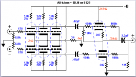
Found the diagram of the original design, in good old Tubepad:
As you can see from studying this pretty basic MC stage the design criteria are obvious:
No input cap, as low noise as possible, no inverting signal polarity and enough gain to match an existing MM phono stage.
In theory there are lower noise valves out there that could reduce the number of //ed triode to two. In theory.
The PS is dated and truth be told was designed to be as cheap as possible. I'm sure we can do better nowadays.
Forget the BF244A, it's obsolete as is it's successor the BF245A J-FET. No big deal, all you need to keep in mind for this particular circuit is the Idss of this device.
Ciao,
Last edited:
No partition noise, and a similar transconductance at 1/5-1/3 the current
Thanks SY
Speaking of design criteria and Mr. Paravicini, here is on of his for Frank
“…it is called the P52 because there are 52 valves in it! There are 20 ECC83s for the phono moving coil, paralleled to get noise down and provide a good overload margin.”
George
Sound of one FET clapping
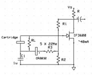
Pass Labs was kind enough to send me some samples of the exotic IF3600 JFET’s and I finally am getting a chance to try them out in a Zen like circuit. It looks practical to get around 30dB of gain at ~.25nV/rt-Hz noise. I am playing around with putting a coin cell in the bias circuit so there is no source resistor at all and a very simple self biasing scheme works to reject the aging of the voltage on the cell. At pico-amps of drain I would expect the battery to last its entire shelf life without replacement.
The amusing question is, is the capacitor in the signal path? It does not block DC if the cart had any and from sim it acts just like cart and the source are both grounded which in this case would burn out the FET. The bias loop does set the low frequency cutoff, but at a 110M/1u (times some factor) time constant.
Sorry for no valves.
Attachments
Last edited:
Scott, I'm wondering about hum pickup issues on the interconnect shield with C1 having a pretty high reactance at 50 - 120Hz.. Oddly enough this is very similar to how I bias the driver stage in my power amps which is driven by a floating (at audio, not RF) transformer coupled output in my line stage. It does work. My C1 is a 47uF black gate. Bias is provided by a string of diodes (driven by current derived from the - bias supply) rather than a battery, but otherwise the principle is the same.
I've not found there to be an aging issue with batteries in essentially zero drain circuits. They last their shelf life and then some, in some applications where internal impedance is important I would probably replace them every few years, otherwise I let them go for about 5yrs. (All my current phono stages use battery bias, and one of my power amplifiers as well.)
I've not found there to be an aging issue with batteries in essentially zero drain circuits. They last their shelf life and then some, in some applications where internal impedance is important I would probably replace them every few years, otherwise I let them go for about 5yrs. (All my current phono stages use battery bias, and one of my power amplifiers as well.)
Hi,
Further to the schematic as posted in post #2:
In order to be able to build this by everyone we need to solve a few minor problems.
First of, as mentioned above, the BF244A J-Fet that was used as a CCS is no longer available so we need a replacement that is easily available to everyone around the globe and if we can do better than the ole BF244 then I'm all ears.
Secondly, the heater supply could do with a better reg as well. But, which one and why? Again, I'm all ears.
Thirdly, the cap multiplier using the MPS14A (at least that one's still around) may well benefit from something more noble than a cheapo electrolytic cap. If so, then again I am all ears.
Once that's sorted I will propose a balanced version with a balun quite similar to John Broskie's circuit discussed here:
Page Title
For those who recognize it, and I'm sure some will, don't panic. The requirements for a mic headamp and those for a MC headamp are quite similar.
For the moment I'll stick with the ubiquitous 6DJ8 as it's low enough in noise once //ed and has just enough gain not to overload a MM phono stage.
Although I wonder if going balanced won't up the gain too much after all....
Of course I won't leave well enough alone and add my own twist to the idea but basically I think I'll have the balun in a separate casing, using its own dedicated and regulated valved PS so it can be put close to an existing MM phono stage.
In that way the benefit of running a diff amp can be exploited to the full, the umbilical cords will carry DC and balanced signal so it should be well shielded from interference.
And the MC headampcan be tucked away close to were it belongs: the TT.
As the balun will be a stand alone unit it can also be put to good use for those fiddling with their DACs. Now, isn't that a good idea?
I'm well aware that some are allergic to paralled valves but if it works for mic amps then why not for a MC cart?
The basic circuit shown in post #2 has served me well for many, many years and has hosted the top of the crop MC carts with no audible noise of its own.
It behave as a good unit should: you just forgot it was there.
Me, I'm a bit of a control freak, the idea of depending on the performance of a single tiny little xformer for the entire reproduction chain makes me uneasy.
As I'm spoilt by the finest OTL amps, the mere idea of that xformer in front of the chain.... You get the picture.
Besides that, I've never listened to a single one that I considered flawless so there you go.
Once we get this all sorted I may try some more exotic valves (you have to before they're all gone, right?) and hopefully reduce their number by two. Less is more or so I'd hope.
As SY suggested in another thread, I'm all for the idea to make his an "Open Source" project". So, everyone's welcome.
Just keep in mind I need your help as well and I only have two hands and half a brain, so one thing at a time, please.
The nice thing about it, IMHO, is that even the entry level MC headamp is quite "high-end" as it is. It doesn't cost an arm and a leg to build and every step up can intrinsically evolve from a single basic unit. Now, ain't that cute or what?
Oh, before I forget: I said I want to keep it simple so if solid state gizmos need to be added they have to justify their presence. If it can be done with a valve I'd rather use a valve. Other than that I bark but rarely bite.
So, there you go gents. The floor is all yours.
Ciao,
P.S.: Forgot to insert some pixies:
Last edited:

- Status
- This old topic is closed. If you want to reopen this topic, contact a moderator using the "Report Post" button.
- Home
- Source & Line
- Analogue Source
- MC head amp stage(s) using tubes.