OK, I found some site which let to calculate a LC -filter by few given paramaters. I picked a Chebyshev 8th order filter (ripple 0.01, corner 48kHz).
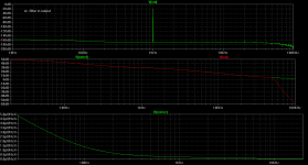
1. I placed the LC -filter just before final output and made some simulations, then
2. moved it to the input part just after the load components (i.e. before the input to LT1028) and made same simulations. Results attached.
Which is the right place for LC -filter, 1 or 2 or is it better to be somewhere else?
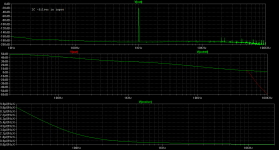
Attachments
The LC filter is supposed to be on the supply rails of the LT1028. Therefore there will be two, one for each polarity of supply. I'm not sure any difference will show up in simulation as few opamp macromodels handle supply rail currents correctly.
I remembered that LC filtering was used on the USB supply rail to the ODAC but when I went to link to the schematic, I got an error as if that pdf had been moved. Hence no example to show you.
I remembered that LC filtering was used on the USB supply rail to the ODAC but when I went to link to the schematic, I got an error as if that pdf had been moved. Hence no example to show you.
The LC filter is supposed to be on the supply rails of the LT1028. Therefore there will be two, one for each polarity of supply. I'm not sure any difference will show up in simulation as few opamp macromodels handle supply rail currents correctly.
I remembered that LC filtering was used on the USB supply rail to the ODAC but when I went to link to the schematic, I got an error as if that pdf had been moved. Hence no example to show you.
Thanks!
Now that I know where to implement the filter I'll keep searching if there are some examples available.
About those noise results I got ... are those OK (different units between LTSpice and LT datasheet) ? Got ~221 nV/Hz½ for 1kHz (measured between 999.99Hz-1.01kHz).
Couple noobie questions about voltages and currents:
- should I use cartridge output voltage (2.0mv 1kHz 5cm/s (or 5.6mV 1kHz 10cm/s)) or measured turntable output voltage as a parameter in SINE() command (SINE(0 0.002, {freq})?
- which would be suitable output voltage (now it is ±200mV (LT1010 outputs the same))
- which would be suitable output resistance when my intention is to connect the pre-amp to USB audio interface which offers three different type inputs ... 1,5k mic-preamp inputs, 10k line level inputs and 1M HiZ inputs?
-- how this final output resistance can be measured in LTSpice and if needed, how it is constructed/adjusted
LC Technology uses this low noise version in their phono RIAA stage together with an AD844still doesn't make low noise bjt Inoise any better with mm coil's high Z
~1 nV heavy bias bjt inputs LT1028/AD797 are really only OK with low Z source less than few 100 Ohms
Scott's AD743/745 would still be the winner - if AD still wanted to make them (seems they do but under protest Product Status:Not Recommended for New Designs)
L C Audio Technology / RIAA/MC Amplifier
- Status
- This old topic is closed. If you want to reopen this topic, contact a moderator using the "Report Post" button.