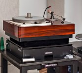
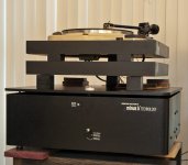
My seismic turntable platform:
In my early years of interest in high fidelity, my ‘listening room’ was on the second floor of a house built in 1916, which was 2 short blocks from a major railroad line. That should give you a hint of where this is going. As I moved up the ladder from VM changers with ceramic cartridges to a Dual 1019 and then a Thorens TD-125 that could handle <1 gram VTF magnetics, the audible effects of a passing freight train became, shall we say, intolerable. As my playback equipment got better, the vibration effects went from a very noticeable warble to groove jumping (watch out for flying tonearms). My first attempt at isolation was to perch the equipment cabinet, which was made of ½ inch walnut plywood and quite heavy, on 4 rubber blocks. This helped, but was still inadequate.
The severe movement of the turntables horizontally from the trains and the vertical sensitivity to footfalls on the second story wood floor was beyond the design limits of either the 1019’s or the TD-125’s spring suspension. Logically, the solution called for an external suspension mechanism, or ‘seismic platform’, that has these basic properties:
1. A natural resonance frequency that is much lower than the natural resonance frequency of the turntable’s own spring suspension. The intent here is that the seismic platform isolate the large magnitude horizontal and vertical floor movements, and leave the turntable’s own suspension deal with the higher frequency vibrations that it was designed for. The seismic platform should deal with and mitigate all the floor-born lateral and vertical shaking, including footfalls.
2. Any residual motion that does get passed on to the turntable must be at or below the natural resonance frequency of the seismic platform, and must be substantially planar, that is, not inflict any tilting moments on the plane that the platter and armboard are in. The intent here is that the operation of the seismic platform during a disturbance not cause the platter and armboard to ‘tilt’ under the tonearm, which could cause the VTF to vary during the disturbance.
3) Ideally, the horizontal and vertical natural resonance frequencies of the seismic platform should be independently adjustable or tunable, through selection of materials and dimensions of key components.
One thought was hanging the turntable base from a long spring, suspended from the ceiling. This would certainly satisfy Properties 1 and 2, but trying to keep the turntable from swinging and yawing after cueing a record appeared to be an inescapable problem. A technique currently popular is mounting the TT to the wall. This might have helped with mitigating footfalls, but wouldn’t help when the whole house is shaking sideways! Other brute force approaches using 200+ pound slabs of granite or concrete would be too difficult to navigate through doors and up stairways. Plus, the mass would still have to be suspended or floated in some manner that satisfies Property 2.
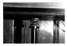
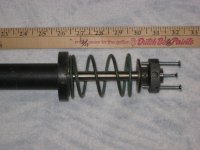
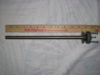
I came up with the seismic platform solution around 1972. My several moves since then eliminated the need for a seismic platform, so I disassembled it and put it in storage. I found the key parts the other day in the garage, with some rust and solidified grease, and decided to start a new thread in case this method fills the bill for someone else in a similar boat, or it might spawn some other useful ideas. The easiest way to understand the concept of how this seismic platform works is to imagine the turntable attached to the top of a MacPherson strut such as used in a typical front end automotive suspension. The piston moving up and down absorbs footfalls and vertical ‘trauma’. The spring rate is chosen so that, when combined with the total mass of the complete turntable assembly, the natural resonance frequency of the system is on the order of 1-2 Hz. Think of a car with worn out shocks going down the freeway, slowly floating up and down after it goes over dips in the road. To take care of horizontal ‘trauma’, the entire strut assembly is mounted on a spring base so that the turntable perched at the top can rock back and forth, at a natural frequency of no more than about 1 Hz. Note that although this rocking would seem to violate constraints outlined in Property 2, a horizontal movement of, say, ¼ inch on a 30” high strut would result in a planar tilt of only 0.5 degrees, and would occur at no greater than 1 Hz, which is easily followed by the tonearm. In practice, the actual horizontal movement was much less. How effective is the seismic platform? Before, passing trains made records unplayable (groove skipping in extreme cases). After, passing trains had no noticeable effect, even with tracking an ADC XLM at 0.6g VTF. In fact, I could do a skip jump in front of the seismic stand with hardly any noticeable effect. The effectiveness of the isolation was stunning. I found a couple of original photos of the platform, and I took some more of the disassembled parts to help you visualize how I put it together.
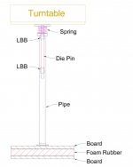
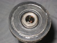
The key element in keeping the platform motion ‘substantially’ planar is the attached die ejector pin whose vertical motion is constrained by a set of linear ball bushings set in a 1” galvanized steel water pipe support. The platform in my case was a piece of ¾” particle board that I made into an integral part of the TD-125 base. The trick in keeping the natural vertical resonance frequency of the platform and turntable low is finding a coil spring with a soft enough spring rate (F = -kx) to work with the mass of the complete TD-125 ‘table, including wood base and arm. In this case I found that a hydraulic servo piston release spring out of a 1966 Chrysler automatic transmission turned out to be perfect for the job (don’t ask). You will have to be inventive to come up with the right spring for your platform. I used a ½” die ejector pin, which is a close tolerance shaft that is ground slightly undersized, and has a ‘hat’ that can simplify attachment methods. I used a v-belt pulley with a ½” bore to provide a flat surface for attaching the die ejector pin to the bottom of the ‘table platform. Note that the pin must be located directly under the center of gravity of the entire platform, base, and turntable assembly. The linear ball bushings are equipped with optional resilient rubber mounts and are held in place inside the pipe with allen head setscrews. The resilient mounts allow the LBB’s to float and be self-aligning. Barely visible in the second photo, just below the pulley, is a soft foam collar that serves as a dust shield for the top LBB, and provides a minimal amount of damping for vertical motion.
The base is probably the easiest part of the seismic platform to build. It is simply 2 square pieces of ¾” particle board with a piece of 1-1/2” thick soft foam rubber sandwiched in between. The dimensions of the boards combined with the characteristics of the foam determine the natural horizontal resonance frequency of the system. The total weight of the stand plus turntable, spread over the area of the boards, was just below the ‘crush’ strength of the foam. Under normal conditions the foam is uncompressed, and the seismic platform stands neat, straight, and rigid, but provides just the right amount of ‘give’ when things start shaking. It was stable under all conditions, and there was never any danger of toppling over with the heavy turntable on it.
I procured the parts ‘before internet’, got the die ejector pin for free from a relative who worked in the tool & die industry, and I don’t remember what I paid for the LBB’s. I did some web searching and found that Thompson still makes the same LBB’s I used, and I found an online source for die ejector pins. Links for these are posted below. Unfortunately for the DIY’er, I don’t see any other way of building and tuning one of these except by trial and error. From my experience, for the system to work as advertised, it is essential to get the natural resonance frequencies for the vertical and horizontal movement well below the natural resonance frequencies of the turntable suspension, and I would say the lower the better. Another essential point to be mindful of is that the diameter of the shaft or pin you buy must be no larger than the specified internal bore diameter of the LBB. The movement of the pin in the LBB’s must be substantially friction-free. A tight fitting or oversized pin will pre-load the bearing, and the resulting ‘sticktion’ would be a deal breaker for this application. Ideally the pin would be 0.0005” undersize.
Damping: The inherent self-damping properties of the foam and the light grease used in the LBB’s turned out to be ideal. Less is more - I would not try any of the gel-foams or memory foams available today, nor would I intentionally try to add damping to the system.
Areas for improvement: The only design deficiency of any consequence that I encountered was the lack of a ‘rotation restraint’ mechanism. The platform will exhibit a damped oscillatory yaw that dies out in a few cycles (winding and unwinding of the coil spring) if you apply a heavy hand when cueing up a record, but this is avoidable if you use a light touch and poise. I never bothered to do anything about this, but I have a few ideas if anyone wants to pursue it. As far as I can see, the seismic platform should work with non-suspended turntables as well, although the choice of system natural resonance frequencies may be governed by different issues.
Links:
Ejector Pins buy online at Plastixs.com
http://www.thomsonlinear.com/websit...ar_guides/linear_bearings/precision_steel.php
Ray K
Attachments
Very interesting. If you look at some of the vibration tables sold for delicate optical/laser work you will see a similar style workings.
If you remember taking a pool cue and trying to balance it on your finger, the goal is move your hand to keep the top steady. Your hand is moving like crazy but the top stays stable. Length is a key component that is hard to accomplish in a regular TT design
This is how some of these tables keep side to side motion stable.
Some do it electronically or passively.
Regards
David
diyrayk,
When will we see your new thread on the Rabco SL-8E tonearm?
Working on that...
...thought I'd get everybody stabilized first...
I built this over 40 years ago. Sorry, I don't remember what I paid for the parts then. I provided links for current parts sources, check them out.
If you have a concrete floor, you pretty much don't need one of these. I disassembled my platform and put it in storage when I moved to a house where I could support my turntable on a concrete floor. I posted my design after reading the many stories of others who do have difficult floor vibration issues. This thing really works well.
If you have a concrete floor, you pretty much don't need one of these. I disassembled my platform and put it in storage when I moved to a house where I could support my turntable on a concrete floor. I posted my design after reading the many stories of others who do have difficult floor vibration issues. This thing really works well.
diyrayk,
When will we see your new thread on the Rabco SL-8E tonearm?
Here it is, I started the thread over a year ago:
Rabco SL8E Photoelectric Servo Control Retrofit
Have you modified/built your's yet?
Ray K
- Status
- This old topic is closed. If you want to reopen this topic, contact a moderator using the "Report Post" button.
- Home
- Source & Line
- Analogue Source
- Seismic Turntable Platform - Stops a Train
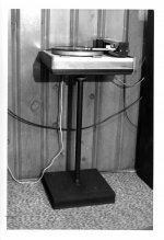
 Reading thru the text I was expecting something massive the size of a small refrigerator. Quite a surprise to scroll down and see such a slim and elegant device.