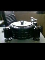
About four years ago i have posted my previous effort in transforming
the legendary DENON DP-80 DD turntable of the eighties into a completely modern shape.
You can see my effort then in the pic below and of course in the "Monsterizing a Denon DP-80" thread.
This was made for a friend living nearby, has kept it's ground proudly
these four years as it's been used regularly, working without a single glitch.
That thread has been touching people's imagination about the ways a
first rate DD table can be transformed.
I have been receiving emails and PM's all this time from people all around the world, wanting to do the same or asking info about how to obtain one.
Since then many DP's have passed through my hands and i have puzzled
my mind about better ways to use this wonderful motor/platter.
Now it's time to post about another effort on the same subject.
This time i had a "carte blanche" on making my absolute best.
I have decided on a better looking shape with differences in metals,
a half size external PSU with all the transformers and modified electronic
boards, modifications in the spindle and thrust plate,modifications in the
split platter construction, an extra metal mat, a custom record weight and
a custom periphery ring.
All these had to mate with a Kuzma 4P tonearm placed on a separate
custom tonearm base...
I did not have the arm in my hands but i have received directly from Frank Kuzma all the relative measurements and specs.
Let's hope i will not mess things up!
Attachments
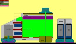
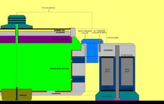
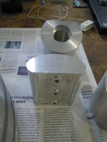
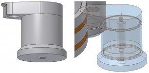
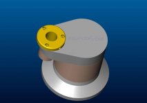
As always, i start with sketches on paper and then make the designs in the computer.
I start with simple designs to see the height,thickness and relative position of the main
pieces with regards to the actual measurements of the original transport.
I will not describe again how a stand-alone DP-80 looks...please refer to the old thread
for this...
Chassis wise...my aim this time was to make it even more streamlined and to create a form that would look elegant regardless of the actual mass of the final unit.
I had decided to use different metals and strategically placed damping agents in an effort to create a chassis that would not impose a sonic character on the sound.
Modifications wise...I have had a great number of DPs passing through my hands for repairs and modifications and when you do this you find very easy to point at the areas that the original can be bettered.
So you can say that i had a set of very fixed ideas about what i would do with this one.
PS:You have to speak greek to understand the last one...it was part of my back and forth discussion with the CNC guys.
Attachments
Last edited:
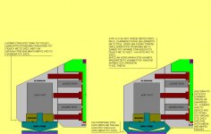
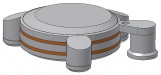
All these scetches were forwarded to a friend who does my CNC CAD files.
We have talked about metal options and weight distribution and each metal's
damping characteristics.
I have decided on a chassis made from machined slabs of softer grade aluminium and leaded iron.
The legs would be cut from a harder grade of aluminium.
These would be hollow in order to create a chamber for lead shot.
The chamber would be permanently closed with a solid disc of bronze that would also serve as a screwing ground for the inox steel spikes.
These would fit into "raised" cups (inox steel) that would provide a streamlined look.
As you see a number of six different metals was used to make sure that each ones sonic character would be counteracted by the others.
Of course i have left space in the design for elastic/damping sheets that would act as flanges to tame down even more the transmission of energy from one metal to the other.
I have used sorbothane, soft grade of silicone, silicone foam and rubber foam.
Attachments
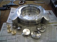
After the metals were ordered, the CNC shop took on.
Unfortunately i do not have access to a 5 axis unit, so some parts of the work
had to be done manually...
I'm used to getting dirty...and this is diyaudio after all!
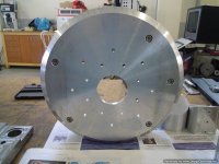
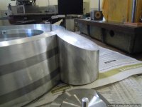
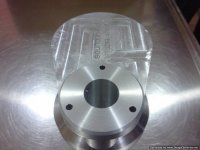
So after some time the parts that form the main part of the chassis were ready.
With long M10(metric) bolts all were screwed together to form a nice heavy "bowl" for the DP-80.
You can see that it is formed by two parts leaded iron and three parts aluminium.
It's about 28 kilos in this part only.
Unfortunately i do not have access to a 5 axis unit, so some parts of the work
had to be done manually...
I'm used to getting dirty...and this is diyaudio after all!
So after some time the parts that form the main part of the chassis were ready.
With long M10(metric) bolts all were screwed together to form a nice heavy "bowl" for the DP-80.
You can see that it is formed by two parts leaded iron and three parts aluminium.
It's about 28 kilos in this part only.
Attachments
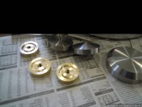
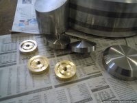
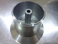
The three supporting legs were cut from hard billet aluminium.
Their slanted top follows the angled shape of the top of the turntable.
Recesses have been cut into their attaching surface for press-fit flange material.
My design was for a hollow form with bronze "bottoms".
Previous tests have shown me that you get a lot of damping with lead shot
and thick gearbox oil and so i have designed an o-ring recess to keep that oil in.
Each leg ends on inox steel spikes and cups.
The cups have raised periphery to completely cover the spikes for a more streamlined look.
Attachments
Last edited:
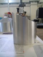
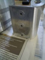
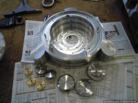
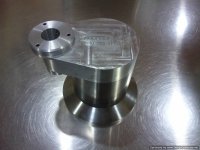
All these were bolted together so that i could take a look at the actual shape of the design.
Each 'leg" is bolted with three M8 screws to the aluminium parts of the chassis.
The screws are inserted from the inside of the chassis and are tailor cut because different exact lengths are needed.
The bronze discs will be press-fitted and glued to the underside of the legs.
The formed chamber will be filled with lead shot and thick oil through the hole that the spikes screw on.
The spikes will be tightened against the o-ring that is captured between the two metals.
The thick o-ring will also act as a damping agent.
The weight of the whole thing (with empty chambers) is 35 kilos.
Impressions so far?
Attachments
-
 DP-80 plinth construction.jpg 3-Optimized.jpg92 KB · Views: 292
 -
 DP-80 plinth construction.jpg 2-Optimized.jpg125.1 KB · Views: 293
 -
 DP-80 plinth construction.jpg 4-Optimized.jpg93.2 KB · Views: 282
 -
 DP-80 plinth construction.jpg 5-Optimized.jpg75.2 KB · Views: 237
 -
 DP-80 plinth construction-Optimized.jpg137.2 KB · Views: 325
It seems that too many people are trying to make another "perfect" DAC...
Anyway...i 'll keep posting...
In the meantime my long distance audio friend was trying to decide on the tonearm
that he was going to use.
The selection was between a SME V, a SME 12" and a Kuzma 4Point.
After some discussions he has decided on the 10" Kuzma.
The DP-80's own chassis is wide,then there is another cm of metal that encloses it, and the arm has to have a collar around it's pivot point...
All that made things difficult for placing the arm on an stand alone external pillar.
It being a 10" arm was not helping much due to the way the arm is made to fit the place of a 9" one.
Frank Kuzma has sent me all the files regarding the positioning of the arm
and also an original collar so that i could make some measurements.
I decided to make my own collar so that i could escape some limitations.
I made several designs around a central idea as i wanted it to look good
except being sturdy...
My CAD guy produced the final files and we were ready for cutting the metals.
Attachments


The tonearm base was made from parts out of different metals again.
I used inox steel for the lower section, leaded iron for the middle part and aluminium
for the top part.
The new collar for the Kuzma was from aluminium.
The middle part was hollow to accept lead shot and oil and sorbothane flanges were
employed to damp resonances even more.
It's weight was 6.5 kilos with the chamber empty and i expect something in the range of 12 kilos with it filled.
The whole thing is to be kept together by a single long countersunk M10 bolt that enters from the bottom,penetrates all the parts and screws on the top plate.
My logo and the arm for which this is made were CNC engraved on the top.
If a new arm is needed i just have to cut a new top plate.
All nice and neat.
Attachments
Last edited:
Very impressive machining. Have you ever thought of taking the motor out of the chassis and install onto your machined plinth? Even with all these heavy duty fabrications, the motor is still bolted to the flimsy aluminum chassis. Of course, if you take the motor out you have to deal with the servo system and remount/reposition precisely the tapehead assembly and extend all the cables separately, sort of like the Kaneta mod with the Technics SP10Mk2 system. I believe the Denon's induction motor is two wires and the tapehead is another couple wires. I think Mitch Cotter did something similar except his is a suspended plinth. Anyway, keep us updated and have fun!
.
.
Last edited:
I understand your point directdriver.
The motor is a three phase out unit and has three wires.
The tapehead used is "stereo"... so four wires.
The positioning and measuring is not so difficult and i have thought of that but the cost of reproducing the complex top area would add at least another 1000 euros to the bill.
The cast top is not so flimsy... it has an around 5mm thickness and it's generously ribbed.
I have puzzled myself about this issue and i have found ways to reinforce/damp it ... to be described soon.
By the way it is all conceived, the exoskeleton will add it's mass and damping on the internal parts.
I am familiar with the Cotter mods and the Kaneta SP-10 mods.
I think that this goes multitudes beyond.
Thanks for watching...please keep commenting...and yes i've had tons of fun!
but the cost of reproducing the complex top area would add at least another 1000 euros to the bill.
I don't think the "top area", assuming you mean the stock chassis that houses the motor, needs to be recreated. I would keep the stock chassis simply as the housing for all the electronics, sort of an outboard power supply, and extend the cables to the main plinth which can be created to your heats content. Unless you are so enamored with the stock flying saucer look that you want to recreate everything including openings for the buttons, switches, and LED, etc... If original aesthetics is a concern then please disregard my suggestion as I understand we all have our desired visuals. I always wanted to do something like that myself but I don't have the tools, skills, and resources to embark on such project. My inspiration is something like the Monaco Grand Prix direct drive turntable or the Micro Seiki DDX-1000, believing electronics should be separated from the motor in DD system. Anyway, you get the idea and I look forward to your future updates.
Once again, happy listening!
I really like both turntables that you mention.
Micro was so much ahead of it's time...
You got me there: I really like the "flying saucer" look and it would be a nightmare to recreate with a CNC all the complex openings and hook up points for all the mechanisms.
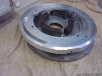
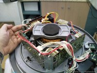
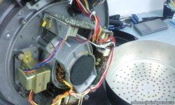
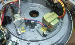
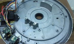
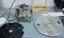
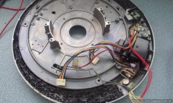
So i chose to keep from the original the top part.
All the control boards / PS boards and transformers will be positioned in a dedicated
power supply/control box and will be connected with an umbilical cord to the turntable.
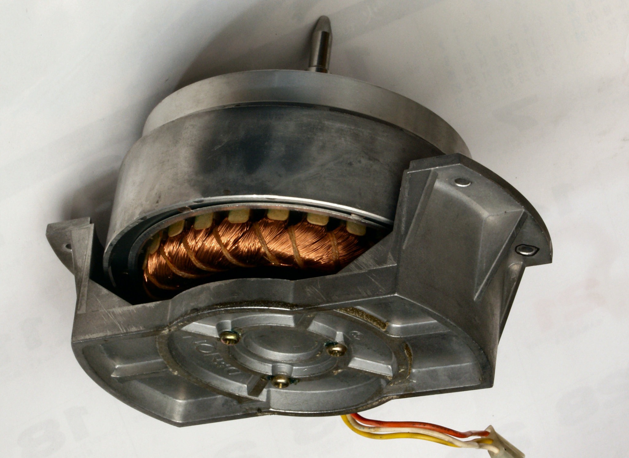
On the stock chassis all is left is the motor the tape head and the buttons.
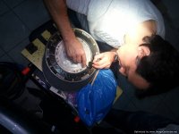
Below are some photos of the process of stripping everything out.
I had to get my hands on the bare chassis and main components to
see what could be done to improve on them...
Micro was so much ahead of it's time...
You got me there: I really like the "flying saucer" look and it would be a nightmare to recreate with a CNC all the complex openings and hook up points for all the mechanisms.
So i chose to keep from the original the top part.
All the control boards / PS boards and transformers will be positioned in a dedicated
power supply/control box and will be connected with an umbilical cord to the turntable.
On the stock chassis all is left is the motor the tape head and the buttons.
Below are some photos of the process of stripping everything out.
I had to get my hands on the bare chassis and main components to
see what could be done to improve on them...
Attachments
Even with all these heavy duty fabrications, the motor is still bolted to the flimsy aluminum chassis.
.
I'm actually in agreement with Soundofvoid regarding the chassis. It dos'nt look flimsy at all. What I do know is that the similar Technics types players, the SP-range, has a rumour of a "ringing" chassis, that many have tried to fix by dampening it in different ways. Also I kind of like the idea of removing as much as possible of the electronics, and place it in an outboard box.
Steen
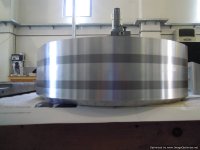
At some point you come to understand that it's not the actual thickness of the metal
(up to a point of course) that damps ringing.
The aluminium bottom plate of the chassis is 40 cm in diameter , 3 cm thick, several kilos in weight and still rings like a bell when you tap it.
The same (to a much lesser degree) goes for the 1.5cm thick leaded iron plates
between the aluminium ones.
However, when these two different metals are screwed tight together the ringing disappears.
They counteract each others characteristics and produce a very well damped mass.
The top part is cast aluminium, the ribs add strength and break ringing and there is
a 2mm black steel cover on top (under the platter) that i used (among other things) to add damping to the chassis by placing a sheet of sorbothane compressed under it.
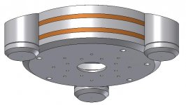
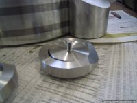
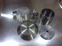
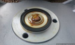
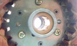
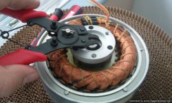
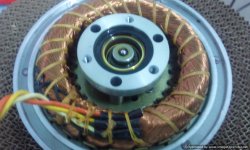
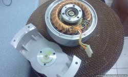
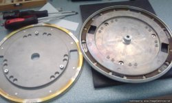
It was time for a check on the heart of the system:the motor/spindle section.
The supporting U part comes of by taking out four screws.
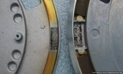
You can see the condition of oil and the debris on the thrust plate after 30 years.
The thrust plate is steel and so is the tiny ball (3mm).
The flange was like new and so looked the axle.
To take the rotor part in hand a circle clip has to be removed.
I decided to renew the self lubricating bronze bushings with longer versions since i was aiming for a much heavier platter.
I also decided to use a completely new thrust plate/ball scheme in search for even lower noise.
I would use a 3 mm thick teflon thrust plate and a 6.7mm ceramic ball.
I didn't like the solidity of the aluminium U part and i started thinking about ways to improve on it.
The supporting U part comes of by taking out four screws.
You can see the condition of oil and the debris on the thrust plate after 30 years.
The thrust plate is steel and so is the tiny ball (3mm).
The flange was like new and so looked the axle.
To take the rotor part in hand a circle clip has to be removed.
I decided to renew the self lubricating bronze bushings with longer versions since i was aiming for a much heavier platter.
I also decided to use a completely new thrust plate/ball scheme in search for even lower noise.
I would use a 3 mm thick teflon thrust plate and a 6.7mm ceramic ball.
I didn't like the solidity of the aluminium U part and i started thinking about ways to improve on it.
Attachments
Last edited:
I didn't like the solidity of the aluminium U part and i started thinking about ways to improve on it.
I like the way you think.
")
It would be nice if it's circular and covers the whole circumference or at least using three point support.
I wish I am a machinist!
PS, Correction: earlier I called the Denon motor as "induction motor" and after looking at more pictures. It is not and looks like a typical AC core motor with magnet and using tapehead servo. I am familiar with some of Denon's earlier models which I opened before and they are induction motors.
- - - - - - - - - - - - - - - - - - - - - - - - - - - - - - - - - - - - - - - - - - - -
Here's a wonder Japanse website that show repairs of everything, including Denon turntables.
A repair from 2002.
A repair from 2008.
Check them out.
.
Last edited:
I know this japanese site of the repair shop from the vintageknob.org!
It seems that we all have the same habits...and like the same things.
I wish i was a machinist and an electrical engineer too!
It's good that i have friends that have these skills and help me with my crazy ideas!
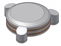
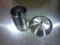
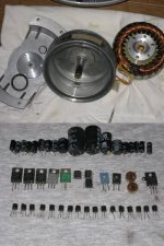
Now, regarding the platter that is a two part design:
The lower disc fits securely (conical shaped hole) on the axle and the top part is suspended with three leaf springs and damped at the periphery with a sponge like material...which after all those years has deteriorated and is completely useless.
I did like the sandwich approach on the platter but i had problems to solve.
I was going to use an extra metal mat and a periphery ring to add weight
and inertia and that would alter the parameters of the suspension/damping.
I have decided to keep the leaf springs and use as a damping agent, a soft (grade 40) sorbothane layer that would always be in contact with both parts of the platter.
My tests proved very rewarding and i decided to do it this way.
It seems that we all have the same habits...and like the same things.
I wish i was a machinist and an electrical engineer too!
It's good that i have friends that have these skills and help me with my crazy ideas!
Now, regarding the platter that is a two part design:
The lower disc fits securely (conical shaped hole) on the axle and the top part is suspended with three leaf springs and damped at the periphery with a sponge like material...which after all those years has deteriorated and is completely useless.
I did like the sandwich approach on the platter but i had problems to solve.
I was going to use an extra metal mat and a periphery ring to add weight
and inertia and that would alter the parameters of the suspension/damping.
I have decided to keep the leaf springs and use as a damping agent, a soft (grade 40) sorbothane layer that would always be in contact with both parts of the platter.
My tests proved very rewarding and i decided to do it this way.
Attachments
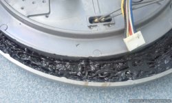
First thing i did was fill up the peripheral cavity of the top chassis with liquid bitumine.
You can buy it in cartridges (just like silicone).
It starts up as semi liquid substance mixed with fibers of some kind and cures gradually to a state that mimics sorbothane.
It's a bit messy but stops any ringing...a solid "thud" is heard when you tap it.
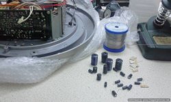
Then it was time for taking out all the old and suspect parts from the boards.
New equivalents were used with a bit uprated capacities (all long life 105 deg)
in the PS section and regulation and more powerful transistors to cope with the heavier loads.
An order was made for the PSU box so that i could place the boards in, the same way that they were in the original chassis.
You can buy it in cartridges (just like silicone).
It starts up as semi liquid substance mixed with fibers of some kind and cures gradually to a state that mimics sorbothane.
It's a bit messy but stops any ringing...a solid "thud" is heard when you tap it.
Then it was time for taking out all the old and suspect parts from the boards.
New equivalents were used with a bit uprated capacities (all long life 105 deg)
in the PS section and regulation and more powerful transistors to cope with the heavier loads.
An order was made for the PSU box so that i could place the boards in, the same way that they were in the original chassis.
Attachments
- Status
- This old topic is closed. If you want to reopen this topic, contact a moderator using the "Report Post" button.
- Home
- Source & Line
- Analogue Source
- My new effort on making the ultimate DP-80