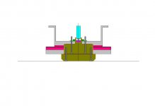
I had decided on the way that i was going to modify the original U part that supports the motor.
The whole thrust plate area was to be ommited and new one would be attached to the U part.
This time it was a teflon thrust plate and a ceramic ball twice the size of the original one.
Under the teflon a layer of medium hardness silicone was used to provide a level of
compliance to the system.
All this was to be placed inside a massive round block of bronze that would go through the original underside bowl and the bottom aluminium plate.
The bronze was to form a "bathtub" for oil up to the height of the ball- everything completely immersed in it.
On the first bronze part, another massive piece of bronze (ballast weight) was to be attached with an intermittent flange
of sorbothane to quiet things down even more.
All this would hang about 1 mm over the turntable's resting platform.
I had to make exact measurements for all these and so i had to test assemble the whole thing together.
It looked nice.
Attachments


Last edited:
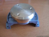
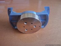
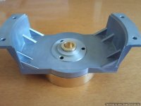
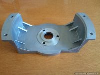
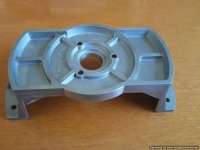
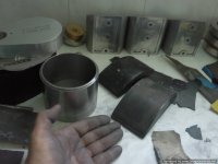
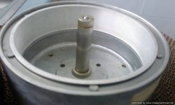
I knew it was a bold move because if something went wrong i would be left with an unusable turntable but stuck to my intentions and sent it out to the CNC and prayed for the results.
A week later i had the pieces in my hands and -thank God- everything went as planned.
The U part was cut carefully and out went the original thrust plate but enough
of the original was left to press the rubber seal securing from oil spill.
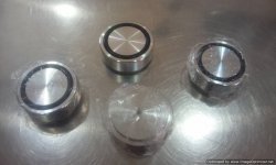
Two new bronze pieces were cut, one to substitute the missing part
and form the place for the silicone/teflon/oil tub and another to attach
on the previous one just to add mass to this critical part of the turntable.
Here are the pics:
A week later i had the pieces in my hands and -thank God- everything went as planned.
The U part was cut carefully and out went the original thrust plate but enough
of the original was left to press the rubber seal securing from oil spill.
Two new bronze pieces were cut, one to substitute the missing part
and form the place for the silicone/teflon/oil tub and another to attach
on the previous one just to add mass to this critical part of the turntable.
Here are the pics:
Attachments
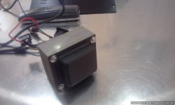
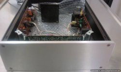
The all aluminium box arrived and looked pretty good.
It had 4mm thick panels all around anodised in black and a nice 8mm thick
front panel anodised in natural silver color.
The fascia was to be modified to my tastes as i wanted things engraved and the 4 screws hidden...
but it was okay for a starting point.
I had made the order on one that could take the whole Π shaped
board assembly as it was placed in the DP's underside plus enough room
for an 80 Watts down converter to 100 VAC, a new bigger transformer to power
up the motor and electronics plus a generous AC filter.
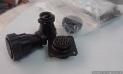
A massive umbilical cord would exit the bottom of the turntable and fit
to the back of the control/PS box with a twist/lock multipin (28 contacts) connector
with gold tipped contacts.
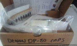
I had made my orders and things started to gather in...
It had 4mm thick panels all around anodised in black and a nice 8mm thick
front panel anodised in natural silver color.
The fascia was to be modified to my tastes as i wanted things engraved and the 4 screws hidden...
but it was okay for a starting point.
I had made the order on one that could take the whole Π shaped
board assembly as it was placed in the DP's underside plus enough room
for an 80 Watts down converter to 100 VAC, a new bigger transformer to power
up the motor and electronics plus a generous AC filter.
A massive umbilical cord would exit the bottom of the turntable and fit
to the back of the control/PS box with a twist/lock multipin (28 contacts) connector
with gold tipped contacts.
I had made my orders and things started to gather in...
Attachments
Last edited:
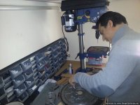
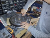
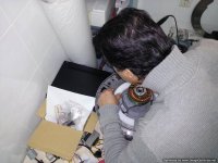
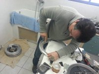
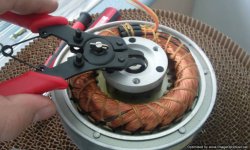
Don't think that everything can be done by machines.
Since it's a mix of the old and the new, many times the process seeks the human labor to make everything fit.
For example parts need to be sanded down, and drill tap and die needs to be done to fortify specific areas that were not supposed to hold the mass that they do now...
There is a lot of my sweat in the details...
Attachments
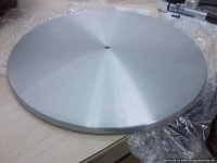
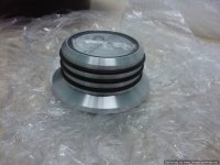
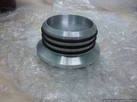
I had a plan about using a periphery ring but the original platter was too shallow
for a competent design.
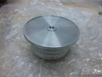
So i thought about an extra metal mat that would give me enough height to use a periphery ring.
I was aiming at around 2000 grams weight and i needed about 10 mm raise.
I designed it with a curved top edge so that the periphery ring would fit easily on it.
Here's what i got:
for a competent design.
So i thought about an extra metal mat that would give me enough height to use a periphery ring.
I was aiming at around 2000 grams weight and i needed about 10 mm raise.
I designed it with a curved top edge so that the periphery ring would fit easily on it.
Here's what i got:
Attachments
Last edited:
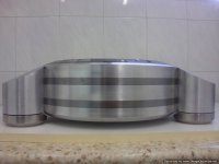
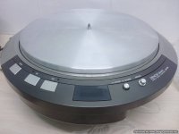
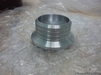
Now it was time for the periphery ring.
I designed one out of inox steel and i wanted to keep it under 1.5 kilos.
I had to take into account the extra metal mat as the ring would position itself
by "hugging" around it.
Plus i wanted it to look as an integral part of the turntable so it's external diameter would be up to the point of the dark grey area surrounding the buttons.
I tried to position most of it's weight under the LP level to aid spindle stability.
It came out pretty good and it's weight was right up to 1350 grams
This is what it looked like:
Attachments

Thank you directdriver!
To be honest i was expecting more interest and questions since i see from the stats many people viewing this thread.
I guess people just wait to see the final outcome and then they will reveal their thoughts...
Anyway...to be continued!
To be honest i was expecting more interest and questions since i see from the stats many people viewing this thread.
I guess people just wait to see the final outcome and then they will reveal their thoughts...
Anyway...to be continued!
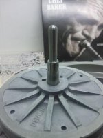
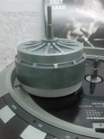
All looked nice and tidy with new metal mat and periphery ring.
However the increase in thickness of the whole platter eliminated the
protruding spindle for the center of the LP.
That meant that the center axle had to be elongated.
I wanted it a good 10mm longer to clear the record and help the positioning
of a record puck.
So, out came the rotor part of the motor and went for an "add on" job.
It was carefully cut at the point it starts to get conical,
a long hole (about 1.5cm) was cut into the remaining part and the new longer part was tightly inserted.
Now i had the height i wanted.
See it in comparison with the original:
Attachments
soundofvoid,
Like a seed, we need to spread vinyl all over the world. There are other forums to spread the vinyl message such as audiokarma to name one. Of course diyAudio is one of the best. You and others are making a great contribution. Keep up the good work that you do.
Like a seed, we need to spread vinyl all over the world. There are other forums to spread the vinyl message such as audiokarma to name one. Of course diyAudio is one of the best. You and others are making a great contribution. Keep up the good work that you do.
Thank you sir!
Diyaudio is my first choise for posting and this is my third detailed thread about turntable transformation in this forum.
I like friendly people and nice conversations about the hows and the whys of audio modding!
I just wanted to say that I've been following this thread for some time now. It is fascinating to watch what can be done when a creative designer is given full access to a modern cnc shop. Awsome!
-Steve
I truly enjoy your thread. One thing I like about this is that all the separate step by step pictures de-mystify the idea of direct drive turntable. You're making it simple for some people who rarely have a peak at the actual motor and its relationship with the platter and how it's put together. It's a deconstruction process. Had the quality DD turntables in the 70's and early 80's been more "simplified" there wouldn't be so many misconceptions about the DD genre but instead many Japanese manufacturers packed every gadget imaginable inside one plastic box, especially the budget models, and the overcomplicated features were prone to breaking and have reliability issues. That was when the Linns in the world took over...
Micro-Seiki was really forward looking with their belt drive tables using a separate motor pod and stable platform for the platter with multiple tonearms and they had a profound influence on modern high end BD turntables. It simplifies things and not only visually but conceptually. The 80's were full of Linn or AR copies with all in one belt drive suspended chassis. But in the 90s people started to appreciate the MS style products.
I just wish more DD tables were made that way, so people can see that what's driving the platter is not this noisy, imaginary fast, coggy motor but it's a magnetic system moving the platter at slow speed, 33rpm, with only ONE single moving part, the bearing. It's truly the most simple and elegant way. (Of course the electronics to drive the stators and servo mechanism is another topic altogether.)
In recent years there are some commercial DD products starting to taking this approach like the belt drive genre by using outboard power supply and electronics in a separate box. Belt drive designers have emphasized the quality of bearing for years so it's good to know DD makers are taking notice and developing further like Brinkmann. It comes down to a platter with a magnet underneath and some coils driving it with magnetic force. And paying attention to each component will, not surprisingly, yield good results.
Your thread is a service to the audio community. At least those pictures are entertaining!")
.
Micro-Seiki was really forward looking with their belt drive tables using a separate motor pod and stable platform for the platter with multiple tonearms and they had a profound influence on modern high end BD turntables. It simplifies things and not only visually but conceptually. The 80's were full of Linn or AR copies with all in one belt drive suspended chassis. But in the 90s people started to appreciate the MS style products.
I just wish more DD tables were made that way, so people can see that what's driving the platter is not this noisy, imaginary fast, coggy motor but it's a magnetic system moving the platter at slow speed, 33rpm, with only ONE single moving part, the bearing. It's truly the most simple and elegant way. (Of course the electronics to drive the stators and servo mechanism is another topic altogether.)
In recent years there are some commercial DD products starting to taking this approach like the belt drive genre by using outboard power supply and electronics in a separate box. Belt drive designers have emphasized the quality of bearing for years so it's good to know DD makers are taking notice and developing further like Brinkmann. It comes down to a platter with a magnet underneath and some coils driving it with magnetic force. And paying attention to each component will, not surprisingly, yield good results.
Your thread is a service to the audio community. At least those pictures are entertaining!
.
Thank you all for your good words.
Although i use in my system the Mitsubishi incarnation which is a belt driven turntable
i am thoroughly convinced that direct drive is the way to go.
That is "properly executed" direct drive.
I consider all the problems that plagued cheap direct drives easy to solve
(at least now-days).
Motors are more silent,cogging is not an issue with heavy platters and multi pole or coreless motors, electronics are faster and more reliable, we have access to newer materials and CNC machines that have impeccable precision and repeatability and so on...
The problem is that modern high end manufacturers lack the resources to make
a dedicated motor for this purpose because the problem is to make a motor able to have
high torque at steady low RPM.
There aren't many of these motors around.
And they are not cheap.
And if they do, it ends up as a product costing tens of thousands of $.
It is much cheaper to them to by a motor "of the self" and move the platter with a belt.
They know it's flawed because of the elasticity of the belt but they overcome the problem by using heavy platters or multiple belts-chaos theory...
Regarding the "deconstruction" of the unit:
When you have all the parts right in front of you and know what each one does, it is very easy to understand what can be made better without the economy restrains that mass production brings.
You end up making this and that and the other better (better electronics,more solid,better machined,better decoupled and so on) and all these little differences add up to a BIG difference in the final operation... and sound.
It's like playing chess where each move opens up countless possibilities for the game.
And i love this game!
Last edited:
On to the record puck then!Or is it "clamp"?Anyway....
I had the extra length on the axle for it to secure in place.
Usually i don't make pucks more than 350 grams.
This time i had a periphery ring and this changes things.
The ring adds it weight on the periphery and promotes an upward "tension" on the center of the LP.
So the central weight had to be increased and i chose to make it around 500 grams.
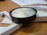
At the last moment we decided to add a spirit level on it (i thought it was a nice touch)
and nothing but the best would go in this one.
I opted for the big Ortofon whose almost 7cm diameter dictated for a simple almost Teutonic puck shape.
The puck was cut from billet aluminium with milled places for the securing of o-rings.
A recess was milled in the bottom for a soft sorbothane flange.
I thought it's design matched the overall turntable shape well and went on with it.
Here's the final piece which i admit myself is the audiophile equivalent of jewelery...
I had the extra length on the axle for it to secure in place.
Usually i don't make pucks more than 350 grams.
This time i had a periphery ring and this changes things.
The ring adds it weight on the periphery and promotes an upward "tension" on the center of the LP.
So the central weight had to be increased and i chose to make it around 500 grams.
At the last moment we decided to add a spirit level on it (i thought it was a nice touch)
and nothing but the best would go in this one.
I opted for the big Ortofon whose almost 7cm diameter dictated for a simple almost Teutonic puck shape.
The puck was cut from billet aluminium with milled places for the securing of o-rings.
A recess was milled in the bottom for a soft sorbothane flange.
I thought it's design matched the overall turntable shape well and went on with it.
Here's the final piece which i admit myself is the audiophile equivalent of jewelery...
Attachments
Have you had a chance to check you're speed stability after adding more weight to the platter yet?
I ask because I might do a rebuild to a JVC QL-10 and was concerned if the servo might over react to this change in weight.
Dr. Feickert't free Ipad/Ipone app and a test record (3150hz) gives a very accurate curve over time on this issue if you haven't seen it yet.
Two big thumbs up on your efforts!
Very nice
Regards
David
Thank you and that's a nice remark!
I am expecting the parts from the paintshop these days and i haven't had the chance to make my final tests.
I have the test record.
I have added the total estimated weight on a normal platter and gave it a spin.
It didn't break a sweat.
This motor is humongous!
I just have to make sure that the power supply will be equally strain free on the long run.
It's good that the DP has a stroboscope to check on actual rotational speed.
It just takes a bit (a tiny bit) longer to lock on speed.
Otherwise it looks perfect.
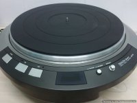
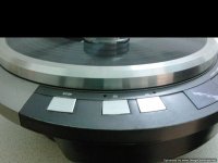
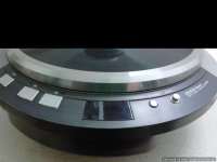
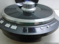
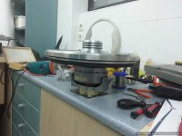
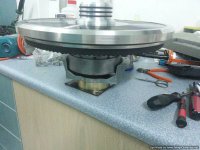
Here are some more pics showing how these parts look on the table.
I did some tests to see if there were differences in noise and movement with the new parts.
I even tested it side by side with an ordinary one.
Even in naked form it proved dead silent and kept spinning way past the point that the original would stop.
I knew i was on the right track.
I had almost double the original weight (8860 vs 4730 grams) in rotating masses and even more rotational inertia.
I knew i had superior damping all the way up to the record height AND superior noise drain because the new thrust plate was part of a free hanging 2+ kilos bronze block.
The new ultra polished ceramic ball with twice the diameter of the original steel one and the teflon thrust plate with silicone support played their part too.
At that time i even came up with a crazy idea of using an even heavier platter (around 13 kgs!) with magnetic levitation so that the pressure on the ball would be between 1-2 kilos...to be tested on the next project!
Attachments

Last edited:
- Status
- This old topic is closed. If you want to reopen this topic, contact a moderator using the "Report Post" button.
- Home
- Source & Line
- Analogue Source
- My new effort on making the ultimate DP-80