Here's a popular tube based design by Salas:
http://www.diyaudio.com/forums/analogue-source/140635-valve-itch-phono.html
And another by koifarm: http://www.diyaudio.com/forums/analogue-source/242855-mini-me-phono-preamp.html
My latest: http://www.diyaudio.com/forums/analogue-source/213769-muscovite-6s3p-tube-phonostage.html
http://www.diyaudio.com/forums/analogue-source/140635-valve-itch-phono.html
And another by koifarm: http://www.diyaudio.com/forums/analogue-source/242855-mini-me-phono-preamp.html
My latest: http://www.diyaudio.com/forums/analogue-source/213769-muscovite-6s3p-tube-phonostage.html
Im actually looking to add a M/M phono input to add to the circuitry of my tube preamp. Right now it is just line in. Id like to add inputs for phono to the case.
What about this CNC MM Phonostage based on National Semiconductors design,one of the best.I am using one since two years.
Regards,
Sachin
Are tube phono preamps have a special sound compared to solid state ones ?
So far i've built Salas simplistic, Eliott P06, CNC MM Phonostage based on National Semiconductors design.
How it sounda tube based one compared to the my solid sate builds ?
I was planning to go for something more advanced like a Pearl 1 or Mini Me tube preamp.
Some experienced opinions would be apreciated.
Thanks!
Are tube phono preamps have a special sound compared to solid state ones ?
So far i've built Salas simplistic, Eliott P06, CNC MM Phonostage based on National Semiconductors design.
How it sounda tube based one compared to the my solid sate builds ?
I was planning to go for something more advanced like a Pearl 1 or Mini Me tube preamp.
Some experienced opinions would be apreciated.
Thanks!
Hi Atupi,
I remember you
An externally hosted image should be here but it was not working when we last tested it.
An externally hosted image should be here but it was not working when we last tested it.
Regards,
Sachin
Im actually looking to add a M/M phono input to add to the circuitry of my tube preamp. Right now it is just line in. Id like to add inputs for phono to the case.
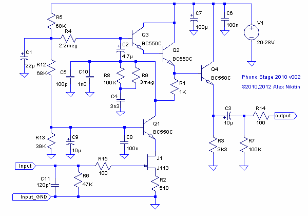
If you can find a 20-28V DC supply inside your preamp (less than 20mA needed), than you can use the simple circuit below.
Cheers
Alex

yes you are right I see the passive equalization. Pretty simple slick solution.
How much gain does this thing boost? I mean it seems there shouldn't be any issue providing 40dB or a little more out of it.
In the MM configuration, as shown, about 39dB at 1khz, in the MC version (replacing the input JFET J1 with 2SK170BL and R2 with 47 ohm) - about 56dB at 1khz, if you bypass R2 with 1000uF - 62dB at 1khz. For the MC version you need to change the input load and remove R15 as well.
Cheers
Alex
In the MM configuration, as shown, about 39dB at 1khz, in the MC version (replacing the input JFET J1 with 2SK170BL and R2 with 47 ohm) - about 56dB at 1khz, if you bypass R2 with 1000uF - 62dB at 1khz. For the MC version you need to change the input load and remove R15 as well.
Cheers
Alex
wow that is pretty slick for a simple circuit like that! I am pretty impressed!

wow that is pretty slick for a simple circuit like that! I am pretty impressed!
It also can produce very good sound - IMHO better than the majority of op-amp based circuits, if you use quality capacitors in it and a good power supply (could be a battery supply as the current consumption is low). This particular version was created specially for DIY and is a variant of my circuit from 1994, produced for many years as the Creek Audio OBH-8(SE) and first published in 1999. Versions of this circuit also were used in many Creek Audio and some Cambridge Audio integrated amps for internal phono stages.
Cheers
Alex
Last edited:
It also can produce very good sound - IMHO better than the majority of op-amp based circuits, if you use quality capacitors in it and a good power supply (could be a battery supply as the current consumption is low). This circuit was created specially for DIY and is a variant of my circuit from 1994, produced for many years as the Creek Audio OBH-8(SE) and first published in 1999. Versions of this circuit also were used in many Creek Audio and some Cambridge Audio integrated amps for internal phono stages.
Cheers
Alex
Yes I think you got the point! A simple circuit like this can be equipped with quality caps and power supply and it sounds accordingly good! Very simple circuit to make for the majority and very simple signal path. Classic circuit with mostly second harmonic's distortion...which is pleasant!
With my little experience I can say opamp based circuit are not match for this in the majority of the opamp based circuits.
Nice circuit!
- Status
- This old topic is closed. If you want to reopen this topic, contact a moderator using the "Report Post" button.
- Home
- Source & Line
- Analogue Source
- Looking for a schematic for phono stage.
