With the µvoltages coming out of MCs I'd rather not take too many chances so I prefer to do I/V conversion as close to the cartridge as I can.
Bit of a contradiction, not? Microvolts coming out and doing an I/V conversion on them.
Hi,
Sure, you want to convert the tiny current/voltage to workable voltage/current.
It depends on how you do this, I suppose.
Cheers,")
Bit of a contradiction, not? Microvolts coming out and doing an I/V conversion on them.
Sure, you want to convert the tiny current/voltage to workable voltage/current.
It depends on how you do this, I suppose.
Cheers,
Havoc said:Bit of a contradiction, not? Microvolts coming out and doing an I/V conversion on them.
Not really. If you use shunt feedback and the cartridge resistance
as the input resistor your effectively using the cartridge current to
drive a virtual earth point.
Due to low R MC's can produce lots of current.
MM typically produce 5mV from 1KR, my MC produces 300uV from 10R.
Loading for MM must be ~50K, current = ~ 0.1uA.
recc loading for my MC = 100R, current = ~ 3uA.
(MC power output is nearly twice the MM)
But using shunt feedback into virtual earth, current = 30uA.
(power from the MC is now 18 times that from the MM)
So there is some logic to it, using I/V conversion.
Still doesn't matter how long the lead is though.
update : just seen F's post, seems this isn't what he meant !
sreten.Hi,
No, you're correct, this was exactly what I meant but I also accept there are other ways to do it.
On paper, no, it shouldn't matter but there are external factors such as EMI and RFI that convinced me to keep leadlength short and put my step-up stage as close as possible to the source.
Cheers,
update : just seen F's post, seems this isn't what he meant !
No, you're correct, this was exactly what I meant but I also accept there are other ways to do it.
Still doesn't matter how long the lead is though.
On paper, no, it shouldn't matter but there are external factors such as EMI and RFI that convinced me to keep leadlength short and put my step-up stage as close as possible to the source.
Cheers,
Use whatever you like. But valves for low impedance..... (OK, I don't like valves, after all I don't use dos anymore as well) Personaly I use a balanced input, with an LM394H for each arm (4 in total) running at about 2mA. Needs to re-wire your arm for it, but very noise resistant.
Hi,
Well, not just any valve of course.
You need to know what you're doing and the ECC88 is a pretty good candidate for the task at hand.
There aren't too many others especially when you start looking at those still in production...
Cheers,
Use whatever you like. But valves for low impedance.....
Well, not just any valve of course.
You need to know what you're doing and the ECC88 is a pretty good candidate for the task at hand.
There aren't too many others especially when you start looking at those still in production...
Cheers,
Guys,
I see emotions are running high
If I can stear the subject of discussion back to original question:
Any suggestiosn on DIY phono cable?
I undestand that MM cartridges have high inductance and impedance. All this make them very dependant on capacitance and resistance of the load.
I see that commercially available cables cost 200 $USD and up. Too expensive for me. I would like to make my own phono interconnect.
So, any suggestions on construction and parts for DIY phono interconnect?
Thanks
Sergey
Dayton, OH
USA
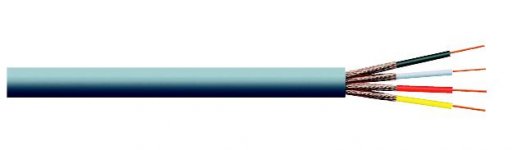
I used to use this stuff :
4-Core Individually Screened :
A four-core screened cable having each core individually screened,
thus keeping crosstalk to a minimum. Stranded cores, 7/0·1mm
copper conductor with yellow, black, red and white polythene
insulation, lap screened and sheathed overall in grey PVC.
Overall size: 5mm
Nom. conductor area: 0·055mm2
Capacitance (core to screen): 95pF/m
Using the screen for turntable ground and the
4 cores for L+, L-, R+, R -, each pair opposite,
and twisted together after tapping the ground wire.
At the time I could find anything with lower capacitance.
Once you tap off the ground wire the remaining wires
need reinforcing with heatshrink or easier electrical tape.
Not the most exotic looking cable I'll admit.
sreten.
4-Core Individually Screened :
A four-core screened cable having each core individually screened,
thus keeping crosstalk to a minimum. Stranded cores, 7/0·1mm
copper conductor with yellow, black, red and white polythene
insulation, lap screened and sheathed overall in grey PVC.
Overall size: 5mm
Nom. conductor area: 0·055mm2
Capacitance (core to screen): 95pF/m
Using the screen for turntable ground and the
4 cores for L+, L-, R+, R -, each pair opposite,
and twisted together after tapping the ground wire.
At the time I could find anything with lower capacitance.
Once you tap off the ground wire the remaining wires
need reinforcing with heatshrink or easier electrical tape.
Not the most exotic looking cable I'll admit.
sreten.Attachments
I should explain that my assumption was the capacitances to
the screen would be in series for each pair, giving I assumed
47pF per metre for each L,R pair.
Specialised low capacitance cable is 13pF/ft, and doesn't suit
the application half as well, L- and R- have to be used for
screening purposes, you need a seperate earth and they
need to be formed into a single run.
sreten.
the screen would be in series for each pair, giving I assumed
47pF per metre for each L,R pair.
Specialised low capacitance cable is 13pF/ft, and doesn't suit
the application half as well, L- and R- have to be used for
screening purposes, you need a seperate earth and they
need to be formed into a single run.
sreten.I use standard microphone cable, the flexible type with cotton inside. Two runs, one for left one for right, with XLR connectors. Both screens connected together at the TT side only, not connection at XLR side. Separate GND wire outside the mic cable, everything tie-wrapped together. You need to have both conductors of a pair inside the same screen, otherwise the twisting is not functional. (I could not make this out 100% on sreten description, but I think his construction gives the capacitance in parallel, not series) Soldered to twisted pair made from 0.1mm laquer insulated wire used in the arm itself.
Next will be the arm wire as before, but directly to the preamp inside the base.
Next will be the arm wire as before, but directly to the preamp inside the base.
sreten said:I should explain that my assumption was the capacitances to
the screen would be in series for each pair, giving I assumed
47pF per metre for each L,R pair.
With further thought I don't think this is true.
At the amplifier the earth wire, R- and L- will all be joined together
on nearly all phono input circuits, so more likely 95pF / Metre.
sreten.- Status
- This old topic is closed. If you want to reopen this topic, contact a moderator using the "Report Post" button.
- Home
- Source & Line
- Analogue Source
- DIY phono cable suggestions.