I did not remove the transistor yet, since I wanted to test how hot it gets while playing. And was curious, so I did it in a quick way. I will remove it when I also do the PSU upgrade. I do not have the equipment to measure the voltage, but from the specs it should be better than the old transistor. And it sounds great I must say ")
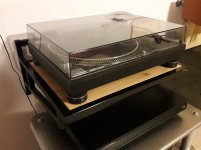
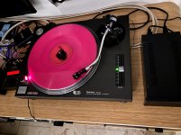
I bought this deck for upgrade purposes, done so far:
- rewire tonearm (cardas)
- 4 new bearings for the tonearm (old were damaged)
- complete recap of the mainboard with high quality low ESR caps
- blue led upgrade of lights
- clean spindle and lubricating it with the right oil
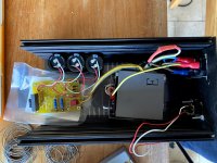
- voltage regulator upgrade with LM2596
How does it sound? Well, hard to say with all these mods (and compared to the state it was in). But it sounds great, have been playing records all day long this weekend. Really having fun, it is very silent already
But if you are curious: these DC Dc buck converter boards only coast a few dollars/euros on aliexpress or similar sites?
Really like the sound already, looking forward to my next mods:
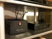
- PSU external
- straight tonearm carbon DIY on sl-1200 basis (found it on art of sound forum; looks really nice! see here for more info)
I bought this deck for upgrade purposes, done so far:
- rewire tonearm (cardas)
- 4 new bearings for the tonearm (old were damaged)
- complete recap of the mainboard with high quality low ESR caps
- blue led upgrade of lights
- clean spindle and lubricating it with the right oil
- voltage regulator upgrade with LM2596
How does it sound? Well, hard to say with all these mods (and compared to the state it was in). But it sounds great, have been playing records all day long this weekend. Really having fun, it is very silent already
But if you are curious: these DC Dc buck converter boards only coast a few dollars/euros on aliexpress or similar sites?
Really like the sound already, looking forward to my next mods:
- PSU external
- straight tonearm carbon DIY on sl-1200 basis (found it on art of sound forum; looks really nice! see here for more info)

Hi,
@#360+361
With that cheap switching reg, I certainly would recommend to either keep the original transistorized regulator in place or to add a good modern linear reg.
I doubt that using such low quality as-cheap-as-possible stuff -possibly built with reused parts- will lead to any improvement at all.
Why do You think that 40V are required??
You are just wasting energy that creates heat power loss, creating problems how to get rid of the heat.
A small decent 24V SMPS and a linear post regulator is all that's needed to give You a clean 21V supply.
That could also be small enough it may reside still within the plinth ... a technically and optically way more elegant solution imho.
jauu
Calvin
Last edited:

Hi,
@#360+361
With that cheap switching reg, I certainly would recommend to either keep the original transistorized regulator in place or to add a good modern linear reg.
I doubt that using such low quality as-cheap-as-possible stuff -possibly built with reused parts- will lead to any improvement at all.
Calvin
That is why I kept the original V regulator in place, the new regulator as an experiment. And see how it performs, technically it has less noise than the original one.
Hi,
Why do You think that 40V are required??
You are just wasting energy that creates heat power loss, creating problems how to get rid of the heat.
A small decent 24V SMPS and a linear post regulator is all that's needed to give You a clean 21V supply.
That could also be small enough it may reside still within the plinth ... a technically and optically way more elegant solution imho.
jauu
Calvin
I do not think 40V is required, it is just what is returned from this external power supply after rectifying. I reused the original transformer, so this is fixed (and no problem for me).
I also looked into the SMPS, very easy to do probably, but less fun
I do not mind an external power supply.

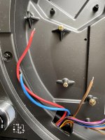
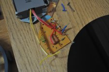
@peppinno: what did you do with the switch wires (shown in attachment)? I'd like to use the switch to enable strobe circuit, but not sure how to accomplish this. I think you also did this?
Yes, let me find the photos... Also 6L6 did that mod
Yes, I know, but couldn't wait to try it, and my ac cable was too short
IMHO Better to put the psu at th left of the 1210, away from the cartridge.
Hi,
@#365 peppennino
You´re of course entited to believe or doubt whatever You want.
In case physics and praxis speak different it might be time to put one´s believes on question
Please explain for example, why a power supply putting out noise and em-fields right in the audio range should be any better than a SMPS putting out noise and em-fields way out of the audible range?
And putting a supply far off from the load may indeed help with regard to em-fields, but its not elegant, neither optically and certainly not technically.
Long traces introduce inductance, create long curent loops, may even lead to regulator instability, spoil reg´s output impedance and may serve as antenna for em-fields.
Rather choose a supply that doesn´t radiate much in first place and keep traces as short as possible and current loops as small as possible.
Compactness is your friend here and also allows to place everything inside the TTs casing ... thereby preserving the SLs elegance in appearance, as well as from a technical viewpoint.
just m2c.
jauu
Calvin
Last edited:
Eric already answered to my doubts. External (smps or linear) power supply remains the best solution if you want the emissions away from cartridge, as Mama Technics does with SP10. Reasonally short cable act as resistor, so as little CRC filter.I would recommend experimenting with ANY SMPS before you spend the time and effort to refit the original transformer. While I am sure there are some that are good (somewhere?), MANY emit all kinds of EMI/RFI garbage, both through their wires and through the air (think AM transmitters). Plug the power supply in, attach a load, then hold it by your cartridge and see if it creates any interference.

A few general ideas that may have benefit -
1) In my experience, the advantage of this PSU mod is mainly (90% ? 95% ?) removing the EI transformer from the chassis and 1M away from the cartridge - this does two things, a) removes the physically vibrating transformer front he chassis, and b) removes the EM field from same transformer away from the cartridge.
2) Regulators should be close to the load. The internal discrete regulator already on the PCB works quite well, changing it might be beneficial, but it’s going to be mild at best.
3) The umbilical from PSU to turntable should be DC
4) I have not experimented with SMPS specifically in regards to SL-1200, but I suspect it would work quite well, as long as it’s removed from the chassis. Having a switch mode regulator regulator in the chassis seems like it would be less noisy than the entire supply, but experimentation seems in order.
Summary - (no new information here... ) The sonic advantages of this mod are huge when the PSU is removed from the chassis of the turntable.
1) In my experience, the advantage of this PSU mod is mainly (90% ? 95% ?) removing the EI transformer from the chassis and 1M away from the cartridge - this does two things, a) removes the physically vibrating transformer front he chassis, and b) removes the EM field from same transformer away from the cartridge.
2) Regulators should be close to the load. The internal discrete regulator already on the PCB works quite well, changing it might be beneficial, but it’s going to be mild at best.
3) The umbilical from PSU to turntable should be DC
4) I have not experimented with SMPS specifically in regards to SL-1200, but I suspect it would work quite well, as long as it’s removed from the chassis. Having a switch mode regulator regulator in the chassis seems like it would be less noisy than the entire supply, but experimentation seems in order.
Summary - (no new information here...
) The sonic advantages of this mod are huge when the PSU is removed from the chassis of the turntable.After I get the Aleph J running
I'm not sure I'm smart enough to gather the 'correct' needed pieces for this. May have resort purchasing a finished product
Pass DIY Addict
Joined 2000
Paid Member
I'm not remembering the configuration that I found in mine, but the transformer secondary should provide about 31vAC. Use your VOM to confirm. I rectified mine in an outboard box and sent DC through the umbilical to the TT. I then placed small regulators in the well where I had removed the transformer that feed the main PCB in the table.
Some images of my modifications are here.
Some images of my modifications are here.
- Home
- Source & Line
- Analogue Source
- Technics SL-1200 DC Power Supply