alister & others,
Some resources and tips,
Go to ebay and look for conventional carbide wedding rings. Some vendors list sizes from 3 to 12. The smallest size I was able to get (just last week) was 3.5----ID .570" OD .685" but will work well for our purpose.
The inner wheel (hub) I made from a 3/4" magnesium alloy rod I got from ebay. Now, my way of adding the axles--- Niffy went with 2 small carbide axles, one for each side of the wheel which works but the alignment is critical and not easily done by diy'ers. I made the hub on a lathe and before I cut the stock off I drilled a #53 hole through the the hub and then used a 1/16" reamer to clean up the hole. I then used a piece of 1/16" carbide rod cut to length (my case .625"). OK, now here is how you make your axles--you put these carbide pieces you cut for the distance you need to fit between the jewel bearings you selected and put them into a Dremel tool or Foredom rotary tool using a 1/16" collet. Now carefully, hold your rotary tool approx 45 degrees to a diamond stone or diamond grinding wheel and grind a point on both end of the axle--much like sharpening a pencil ! The jeweled bearings I used have a 70 or 75 degree angle so a 45 degree angle on the axle will be fine. Now you slide the axle through the hub make sure you have an equal length axle on both sides of the hub, now put a drop of crazy glue on the ends of the hub being careful not to cover the ground ends and you are done. You can refine this technique to your skill level. I am sure the wheel/ hub/axle/jewel part of this arm build is a stumbling block for many trying to make this arm so I came up with this procedure to help sort it out. The actual axle diameter can be converted to a similar convenient metric value.
Carbide rods can be purchased from,
Centennial Carbide 1 800 725 8330 (USA)--very good price,very nice people to deal with.
Jewel Bearings (USA)
Bird Precision 1 800 454 7369 Again, very good price and nice people to deal with.
When picking the bearings, I asked for the largest vee jewel that fit on the end of an 8-32 set screw. I checked their site before posting and there was a problem with their server. Their site is very interesting and informative and they can also supply carbide axles (expensive). I paid $200 for 20 bearings which I think is very reasonable.
I hope this info helps some people and thanks again to "Niffy" for all his time and hard work.
Joe
I've had a browse through eBay and can't find the tungsten carbide rings that I purchased. Several vendors have rings down to US size 3 but I couldn't find any size 2. The prices of the size 3 were all considerably higher than I paid. Looks like I got really lucky. The theoretical advantages of smaller wheels are lower mass and that the centre of mass can be kept lower. They were also perfect for my arm as the size 2 perfectly fitted my carriage. Larger diameter wheels have the theoretical advantage that they should have slightly lower lateral friction. (Larger diameter wheels have lower rolling resistance and the pivot has to rotate through a smaller angle to accommodate the same lateral movement.)
The rings I am using are 2mm wide and run on 4mm rods. This results in the vertical friction of the bearing being higher than the lateral friction. This is actually very useful as it damps the vertical movement of the carriage. Vertical damping needs to be higher than lateral as the frequency of warps that can excite vertical resonance are much higher than that of eccentricity that can excite lateral resonance. Taking the effective masses and driving frequencies together suggests that vertical damping needs to be about 3 times higher than lateral. As luck would have it the vertical friction and hence damping is 3 times as high as lateral for my arm. I think that the level of damping in my arm is probably about perfect as the effective mass test tracks on my test record do not excite the arm at any frequency vertically or laterally.
Vertical friction of the bearing can be reduced by using a narrower ring and smaller rods. 1.5mm wide rings are available through the smallest size available is larger than the 2mm. If these are used with 3mm diameter rods the lateral friction should be about the same but vertical friction will reduce by about 25%. Wether this is advantageous or not is another question.
Niffy
Hopefully this thread isn't too dead and someone might be able to give me some guidance.
I have read through this thread and I am set on building my own linear tone arm. However I have kind of researched myself under the table. There are just way to many variables and tradeoffs to even keep track of.
Here is the deal, I received a free turn table. It is a Dual 502. The thing tracks really well and it seems like a fairly solid turn table, but the arm is not the greatest. I am looking at removing all the components and making my own plinth for it. Ultimately turning it into a DIY turn table.
I am noticing that there have been a lot of design iterations over the years. 1 tube vs 2 tubes, knife edge bearings vs air bearings, and so on. All seem to have their plusses and minuses.
I am trying to figure out what the crowd favorite design is.
I kind of like this design here DIY linear tracking arm
It looks very simple and easy to get right (relatively speaking). Any thoughts/comments?
I am trying to figure out what the crowd favorite design is.
Hello Tjj226,
Not knowing what type of individual you are, or the skills and tools you have, my advice to you is, to never copy what others have built. If I were you, I would look at all the designs, (which you have already done) and come up with your own design. I have designed and built many devices over the years and the main features have always been unique. And don't let anyone tell you, that everything has already been invented. Successfully completing your own design ideas, puts you on cloud 9 every time.
Sincerely,
Ralf
To Straight Tracker. Ralf, what is your opinion as to patenting a new arm design? I followed both threads here, dedicated to linear arms, and concluded, that patenting a new design by independent inventor has no chances to bring financial results. Basically, hi-fi manufacturers are busy with their own designs, and not prone to buy something from outside. Exceptions are well-known inventors, like Frank Schroeder. Am I right?
Walter
Walter
Hello walterwalter,
You are absolutely right in your comments.
There are over eight million patents in the US Patent Office alone, the vast
majority of which will fall by the wayside!
Inventing is the easy part. The difficulties start when you try marketing your invention. The minds of inventors and marketers are diametrically opposed.
A patent application can easily cost you several thousand US Dollars and once you have the patent, you have to pay a "maintenance fee" every four years just to keep it in force. And to make things worse, that "maintenance fee" doubles every four years.
However, you can prosecute your own patent application as I have done in the early 1980s.
I have eight US patents but I only made less than a thousand dollars on one of them.
In October 2017 I finished the design and prototyping of a tangentially tracking tone arm and I decided not to patent it. Since then I have shown it to a number of people, some of whom were somewhat on the sleazy side.
I can't prevent it from being stolen, but I can make sure that I will get the credit for having invented it by making it public in these pages in the near future.
Sincerely,
Ralf
Thank you for reply, Ralf. Yes, I know the main problems, because I've patented myself IMHO mildly commercially perspective design of photo-elecrtically operated turntable auto-stop, that is a universal device, supposedly easy to install and use on the most audiophile turntables (which I use on my Micro turntable for 7 years). For the next one year I've tried to attract manufacturers attention by mailing and e-mailing them, and only one of them answered (that he is not interested), the rest just ignored. Finally, I've made myself and sold about 20 of them, to compensate for patenting, and closed the project forever. Pictures here are just to confirm that some of my ideas aren't that stupid. I'm still pretty sure that it is a profitable product, in case if a well known brand starts making and promoting it. Now it is for free to take, if someone is interested.
Now I build my prototype version of the pivot linear arm, which is different from all other versions, I know about. It is as different, as my auto-stop differs from mechanical arm-lifters (those are IMO clever, useful and underestimated ones). And I'm considering Pro's and Con's concerning patenting it. It only makes sense, if there is a chance to sell it to the well known brand. I'm not a well familiar person to the technical ideas market, and I'm not sure, if the demand on new ideas exists at all among manufacturers.
Sorry for placing that in the tonearm thread, but it is the only place, where I see some highly qualified professionals, with their own experience of patenting and promoting no-nonsense tonearm ideas.
This thread, as well as " Angling for 90° - tangential pivot tonearms" are real delights among all audiophile forums known to me.
Any experience and advice will be highly appreciated.
Attachments
Last edited:
Yes, it stops the motor only. First, I was worried with that, and considered addition of the arm lift. However, experience with working unit showed, what it is not a problem even with the idler drive turntable, if you leave it stopped for a couple of minutes, and not for weeks and months. And stylus in a stop mode, resting in the immovable groove is 100% safe. Keep it simple works very well.
As to marketers mind, I thought that they should be interested in finding innovative, commercially competitive products, nobody else makes yet. That seems to be easier and more profitable, than competing with lots of the similar products, as it mostly is. In that aspect both inventors and marketers interests should coincide. The question is: why marketers do not accept that fact , and are so passive and even resistive. Or, maybe, I'm just not familiar with the correct way of promotion?Hello walterwaltук
Inventing is the easy part. The difficulties start when you try marketing your invention. The minds of inventors and marketers are diametrically opposed.
Sincerely,
Ralf
Of course, I don't mind stupid and questionable ideas.
Walter
Last edited:
Niffy
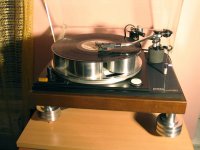
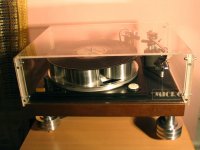
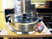
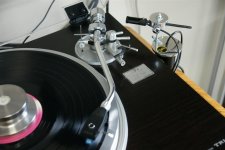
I am new to this thread and to the world of Diy really. I stumbled upon this thread about a week ago and have read it all the way through. I find it amazing that these arms can be built, the knowledge and expertise is incredible. For the most part I can see how these things are or can be constructed but I cannot see how your arm or indeed your deck - which are stunning- are made. How do you do it? I can see how one would construct things out of polycarbonate and carbon fibre but yours are very professional looking and made out of steel or aluminium? Do you make a template out of mdf and have it made by someone or somehow fabricate it yourself. Hopefully it's not to stupid a question. If it's not divulging something that you don't want to share I would be very grateful if you could enlighten me a little.
I will be a attempting a very modest go at this at some point when work is not in the way.
Regards
Jonathan
Hi Jonathan,
I'm glad you like my arm and deck.
The carriage is made of carbon fibre built around balsa cores, there is quite a lot of internal structure that is not readily apparent from the outside. I had the carbon fibre specially layed up with the fibres aligned to my specifications, the alignment of standard sheets was suboptimal. The design of the carriage took the best part of a year. I created a custom program in excel that is very similar to finite element analysis. My aim was to push the bending mode resonant frequency of the arm to above 20kHz, which I pretty much achieved. Most commercial arms have a resonant frequency in the 500Hz-1kHz range and often even lower. The single biggest cause of colouration in most arms is due to bending modes. By pushing the fundamental out of the audio bandwidth virtually all colouration is eliminated. I didn't just chase high resonant frequency blindly. The excel program also calculated overall mass, effective mass, tracking force and tracking force variation due to warps and its effect on warp wow. The arm was designed specifically for the Ortofon 2M black cartridge.
The rest of the deck is mainly made from aluminium and acrylic with the odd bit of stainless steel and a large slab of laminated lead to balance the suspension and to act as an energy sink. As with the carriage sound quality was my primary concern. I kept the subchassis small in order to minimize resonance. The centre of mass of deck is precisely aligned with the suspension. The deck is halfway between being a suspended subchassis design and a solid plinth design with a dedicated isolation platform, taking the best of each approach. The motor is therefore mounted on the subchassis as this is the best place for it.
The entire deck was built by hand by myself. No fancy tools or fully equipped workshop. It was all built on a black and Decker workmate in the corner of my kitchen. Using a pillar drill, router, hacksaw, files and many packs of wet and dry paper. I made many templates from many different materials. The most common being paper that had the design fro the computer printed on it.
I probably spend as much time making jigs and templates as I did actually fabricating. The most important tool I used was patience. If you're planning on building an arm don't start in the morning and expect to be playing records in the evening. Many components took days to make. The entire project took over six years to complete. Worth every second.
I do have a degree in composite engineering that was invaluable in the design process. This degree is however entirely theoretical in nature and I have no training in fabrication techniques. I just worked that out for myself.
The construction of my deck is DIY in its purest form and hope that it inspires others to have a go.
Niffy
Niffy,
Thank you for your detailed response, it is very much appreciated and useful. And very encouraging that you don’t have lathes and array of equipment at your disposal..motivating.
I will definitely have a go at building this arm-a more modest affair but you have to start somewhere. It’s an interesting thing to do and you can listen to your work afterwards.
Keep posting the pictures.
Thanks again.
Jonathan
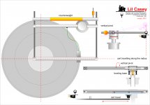
radial rail*- some thoughts
Hi all - first post here, but not new to this amazingly instructive thread.
After a dozen different pivoted arms, including some P.L.T. (working or not) I want to try something like this too. (attachment)
Linear geometry vectors did not convince me, but what if the carriage could travel along a radius? Seems far better, but now vertical movements can be no more faced by the shaft, even the shortest one Revox style. Maybe there is no need to keep them coincident with horizontal ones, so we can explore different solutions: a cart just sliding on a radial rail, a rail fixed horizontally but rotating vertically, a vertical pivot applied to the entire rail instead than to the shaft. (there's no real shaft...)
Could it work? observations and advices really welcome.
carlo
*- Direct driver's thread "Angling for 90° - tangential pivot tonearms" post #1957 #1960 - where this project started from
Attachments
It is, as far as I can tell, not an air-bearing but a passive roller of some kind. From what I can tell from the drawing,I do think , though, that the bearings inside the tube are too small to have low enough friction.Hi, NOCD. I can't see, why it wouldn't work with an air pump. The only substantial problem seems to be very different horizontal and vertical masses. As well, as probable sonic influence of the air flow right near the cartridge. Anyway, it seems worth trying...
The difference in vertical and horizontal mass is only a benefit to my way of thinking.
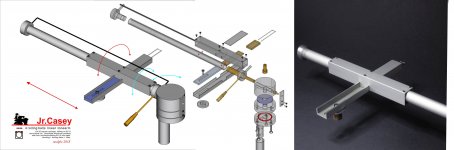
No air pump, no servo please, just passive: the cart uses what maybe you call "linear thrust bearing" in english: balls travel half the space of the cart, always in contact with the rail (= no chattering) and with the least possible friction. Previously tested on a pair of my experiments.
Masses: the horizontal is just the cartridge + cart, less shaft, less counterweight. The vertical seems big - the rail + cart + 2 shafts, + V.P. tube + CW - but acts like those in pivoted TA, so the eff. mass is highly reduced, and with some calcs can be made similar to the horizontal
But before discussing details maybe better to examine the basic idea: could it work?
thanks - carlo
Last edited:
*- Direct driver's thread "Angling for 90° - tangential pivot tonearms" post #1957 #1960 - where this project started from
Hi Carlos, I'm glad that you've already taken up the challenge of making horizontal movement independent from a pivot arm and saw the positive side of the video of that very flawed tonearm and you did not dismissed it right away. It can spawn some good ideas. It is one of very few examples of doing tracking force differently, which include Ralf's design in another thread. I think it opens up new thinking.
One concern about this type of design is the loading on the rail which includes the mass of the cartridge, headshell, and rolling carriage. I think in your case, it seems to be adequate without encountering chatter or contact issues.
I think the arm can be more compact without the dual vertical arm design just for aesthetic reason.
Hi Dd: in spite of my projects, your thread still remains a gold mine for every diyer (and professionals too?)
I had already made this attempt (only half: carriage and rail) interrupted because the results were not too different from those seen in the achievements of friends: stylus bending. Despite a very short lever, and very low frictions the problem of the wrong point of application of the force seemed unsurpassed.
Then that video convinced me to try again: at first designing (without anything convincing) a vertical piston-like movement, then resigning myself to this trivial solution (always the most difficult to find): pivoting the rail.
The constructive problems now guessable are mainly these:
vertical torque on carriage, due stylus drag - modify the linear thrust bearing shape to counteract it.
cartridge compliance, due the very low horizontal mass - unfortunately an increase may bring in even bigger issues.
vertical mass - now the long lever works to our advantage, but everything possible must be done to limit the inertia of the moving masses. I fear that only one shaft would be nicer, but much heavier to get the necessary stiffness
carlo (just italian, not spanish...)
Ralf design comes from another planet...
Attachments
Last edited:
- Home
- Source & Line
- Analogue Source
- DIY linear tonearm