Look what happens with DVM readings as soon as the battery collaps , weird values, same story with a scale I guess .
Put new batteries in and reset the cal. Penny weighs 2.5 grams now. All better now.
Thanx
BillG
mine has a reference weight and I just check it once in a while .
it never let me down so far
another question keeping me busy here , does anyone know about a real good methode to check the azimuth , other than by the eye ?? I have a dual channel scope here , a decent RMS Millivolt meter , test record . but what is the very best methode ?? hope someone can teach me the right trick
THX
Paul
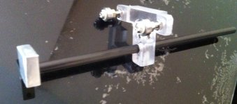
For those interested here is the carriage design and setup. So simple it's ridiculous
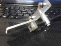
Here's another one , with an additional adjustment this time
Looks great , Colin !
THX
Paul
Attachments
centre of mass/gravity
The cog HAS to be just in front of the pivot. If the cog is directly underneath the pivot the carriage would balance perfectly and there would be no down force at the cartridge. If I remember correctly Colins carriage weighs 30g Inc cartridge and has a 75mm effective length. To achieve a 1.4g tracking force, as recommended for the at120e, the cog needs to be 3.5mm in front of the pivot.
With this design almost the entire mass sits below the cog. This will cause the tracking force to increase as the cartridge passes over a record warp. (if the cog was above the pivot the tracking force would decrease) A slight increase in tracking force when negotiating a warp is probably a good thing.
Looking at Colins latest photo of the carriage (nice work Colin) I would estimate the cog, with the cartridge and counterweight in place, to be about 20mm below the plain of the pivot. A quick calculation would show that when negotiating an average warp at the outside of a record, a warp of about 0.3mm, the tracking force would increase to about 1.43g, an increase of 2.3%. Definitely not enough to misalign the cartridge generator significantly but probably helpful for tracking.
Warp wow with such a short arm and high pivot still worries me a bit but as Colin and Bill have not found this to be a problem I'm probably worrying unduly. A good record clamp will help reduce this problem anyway. In my book it's much better to move the problem of warps to be dealt with by the deck rather than the arm anyway.
Colin
It looks like your homing in on a final design. Are you planning on rebuilding for cosmetic reasons or are you happy with the looks? This is undoubtedly the best thread on diyaudio. Great work
Niffy
Niffy , when we staticly balance the arm w/o the cart + CW attached , the COG is exactly under the pivot ! nowhere else . Of course if we than install the cartridge alone , there's downforce on the stylus as much as the weight of the cart , and the COG moves upfront .
The CW will bring this back into the ballpark depending on it's weight and location . no math applied here at all .
THX
Paul
Last edited:
Niffy , when we staticly balance the arm w/o the cart + CW attached , the COG is exactly under the pivot ! nowhere else . Of course if we than install the cartridge alone , there's downforce on the stylus as much as the weight of the cart , and the COG moves upfront .
The CW will bring this back into the ballpark depending on it's weight and location . no math applied here at all .
THX
Paul
Paul
Sorry misread you post on the previous page concerning cog. You were balancing without cartridge or weight, missed that.
I like to find something that works (like this arm), do the math to find out why it works, then see if it can be improved. Maybe I'm weird but enjoy the math part of design.
My point on the vertical location of the cog was that Colins current arm and the math happily agree with each other.
Niffy
Cog should be ahead if the bearings without cart or counterweight so that you can place to counterweight further back on the wand. Nifty, I think ive got it where i want it, it's easy to build which is important and requires fewer products on the bom. No just to get rid of tooling marks with some filing and sanding, polishing. I like the parts, the carriage is only 4 distinct pieces with fewest connections possible and the arm is almost a one piece minus the alu headshell, less bolts/glue the better.
Colin
Colin
This arm is now stupidly good, there is nary a simpler way to get superb results. As always setup is king, and ultimately it all works together, note the polycarbonate end stub, its important in aiding abolishing hf ringing
Colin
Colin,
can you please tell me the diameter of the tubes? Did you glue them to the aluminium bracket?
Thank you!
I'm sure some will agree with me that a straight tube is the worst to be used for a tonearm , it's the law of nature unfort think of an organ pipe acting as an amplifier .
Than there's also something called decoupling which counts a lot for this matter , using a mix of materials in arm design however is a huge guess for any diy'er , pretty unpredictable . also any joint should be as tight fit as can get , a good reason not to use glue if you ask me .. but press fit connections , even a set screw will not be optimum . those who payed attention to the foto of my tonearm ver.II , using an aluminum cilinder between the polycarbonate bearing carriage and carbon arm tube , have probably noticed the methode of connection between these two parts , no better way to get 2 parts connected
with each other no doubts . I'll also omit the lower set screw in this arm later on , along with a tapered arm tube out of 3 pieces . my gut feeling says it will controll hf better compared with a one piece tube alone . dampening material inside the tube is next step . in all honesty .. I'll report later about differences between different arm structures/materials/joints etc. this is getting realy interesting at this point , and if a simple stick works best , I'll be frank to let you all know . nothing to loose , much to learn 
THX
Paul
think of an organ pipe acting as an amplifier .Than there's also something called decoupling which counts a lot for this matter , using a mix of materials in arm design however is a huge guess for any diy'er , pretty unpredictable . also any joint should be as tight fit as can get , a good reason not to use glue if you ask me .. but press fit connections , even a set screw will not be optimum . those who payed attention to the foto of my tonearm ver.II , using an aluminum cilinder between the polycarbonate bearing carriage and carbon arm tube , have probably noticed the methode of connection between these two parts , no better way to get 2 parts connected
with each other no doubts . I'll also omit the lower set screw in this arm later on , along with a tapered arm tube out of 3 pieces . my gut feeling says it will controll hf better compared with a one piece tube alone . dampening material inside the tube is next step . in all honesty .. I'll report later about differences between different arm structures/materials/joints etc.
this is getting realy interesting at this point , and if a simple stick works best , I'll be frank to let you all know . nothing to loose , much to learn THX
Paul
Last edited:
Forgot to mention that I entirely filled my glass tubes with black silicon compound as well  besides the dampening properties it also is making it sooo very easy to detect dust particals on the rails surface almost impossible with the otherwise transparant and shiny tubes
THX
Paul
besides the dampening properties it also is making it sooo very easy to detect dust particals on the rails surface almost impossible with the otherwise transparant and shiny tubes THX
Paul
Spinning wheel,
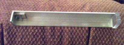
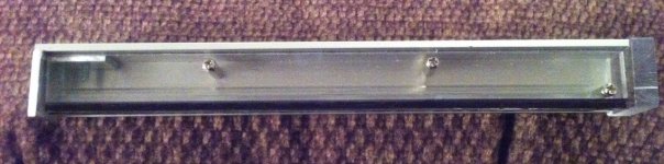
I look forward to your finds, also look forward to to seeing some corfirmation on my finds. Dissimilar materials can be a stab in the dark, but if ive learned one valuable point in the process it's critical where you place the masses. The worst headshell I've found is a flat piece of thinner variety, the best is a block that is taller than it is deep. Less connections the better, and a route for energy away from the arm.
Anyways, back to enjoying some lovely music while I work on my 2nd build for my significant others system.
Colin
I look forward to your finds, also look forward to to seeing some corfirmation on my finds
. Dissimilar materials can be a stab in the dark, but if ive learned one valuable point in the process it's critical where you place the masses. The worst headshell I've found is a flat piece of thinner variety, the best is a block that is taller than it is deep. Less connections the better, and a route for energy away from the arm. Anyways, back to enjoying some lovely music while I work on my 2nd build for my significant others system
.Colin
Based on your experience the headshell you posted at first picture is better than the second picture.Spinning wheel,
The worst headshell I've found is a flat piece of thinner variety, the best is a block that is taller than it is deep. Less connections the better, and a route for energy away from the arm.
Anyways, back to enjoying some lovely music while I work on my 2nd build for my significant others system
Colin
Any chance you made A-B test on them?
I purchased some L profile aluminium, can you let me know how long is your so I can cut it. I want to cut 2 pieces for experimenting (I do not want to cut shorter (to mess it up) then must be.
Are you using some silicon type soft glue between the tube and the aluminium or some hard type of glue like Epoxy etc.?
I have some glass rode (actually tube but with 2mm wall thickness one piece is 7mm other 10mm, I have to go back to the store to exchange the 10mm to a 7mm type
Also I have a triangle shaped with rounded corners glass rod(came out from a long thermometer) probably I will test that to with a decent type bearing.
These triangle glass the thickest side 4mm only.
One thing is sure I want to go with 2 bearing like yours!
Greetings Gabor
Colin,
Qualitative measurements are totally lacking in this thread. I've taken time to look through entire postings. One mention of possible use of test record.
Lots of discussion about mass of components, cart, arm, carriage etc. Much mention of compliance. Entire mass of system may be viewed as masses attached to cantilever suspension. This tiny damped spring with mass of cantilever on one side, and moving mass of everything else on other. Low frequency oscillation of big mass are modulated onto signal picked up from groove, and are stimulated by groove.
Periodically, posts of recordings made from turntables show up. I look at these and see results such as these:

And:

Top pic is from a classic heavy 'S" arm, and second from a linear tracking arm. Primary resonances are respectively at about 8Hz and 14Hz. The relative levels to primary audio band are both quite high. The effects are quite audible, neither is good. All frequencies present in primary signal are accompanied by side bands corresponding in spread seen about fundamentals of low frequency resonance.
When similar analysis is done on CD sources, and other digital sources I get results like this:

Much, very much cleaner.
For given cartridge and moving mass of tonearm system, frequency of primary resonance is inversely proportional to moving mass.
Spring system of cantilever must be stiff enough to support motor structure in linear range, which is optimized for applied tracking force. Contact of stylus is governed by resonance of cantilever. This is influenced directly by mass of cantilever, speed of sound in the cantilever, mass of magnets or coils it is connect to, the damping characteristics of the cantilever, the damping of suspension/spring it is connected to and acoustic impedance of this connection. This isn't an exhaustive description. Modulation of the stylus contact with record surface is source of audio heard directly from playing record. This is readily verified by use of microphone to record the audio emissions.
Anyway, I would be delighted to see some real response recordings of your creations. Comparisons of recording with and without loudspeakers would be interesting to investigate as well. Great comparison would be of recording from record v source for producing record.
Qualitative measurements are totally lacking in this thread. I've taken time to look through entire postings. One mention of possible use of test record.
Lots of discussion about mass of components, cart, arm, carriage etc. Much mention of compliance. Entire mass of system may be viewed as masses attached to cantilever suspension. This tiny damped spring with mass of cantilever on one side, and moving mass of everything else on other. Low frequency oscillation of big mass are modulated onto signal picked up from groove, and are stimulated by groove.
Periodically, posts of recordings made from turntables show up. I look at these and see results such as these:
And:
Top pic is from a classic heavy 'S" arm, and second from a linear tracking arm. Primary resonances are respectively at about 8Hz and 14Hz. The relative levels to primary audio band are both quite high. The effects are quite audible, neither is good. All frequencies present in primary signal are accompanied by side bands corresponding in spread seen about fundamentals of low frequency resonance.
When similar analysis is done on CD sources, and other digital sources I get results like this:
Much, very much cleaner.
For given cartridge and moving mass of tonearm system, frequency of primary resonance is inversely proportional to moving mass.
Spring system of cantilever must be stiff enough to support motor structure in linear range, which is optimized for applied tracking force. Contact of stylus is governed by resonance of cantilever. This is influenced directly by mass of cantilever, speed of sound in the cantilever, mass of magnets or coils it is connect to, the damping characteristics of the cantilever, the damping of suspension/spring it is connected to and acoustic impedance of this connection. This isn't an exhaustive description. Modulation of the stylus contact with record surface is source of audio heard directly from playing record. This is readily verified by use of microphone to record the audio emissions.
Anyway, I would be delighted to see some real response recordings of your creations. Comparisons of recording with and without loudspeakers would be interesting to investigate as well. Great comparison would be of recording from record v source for producing record.
- Home
- Source & Line
- Analogue Source
- DIY linear tonearm