VTF - Stability & Reliability Researched
More research, with 5 photos to enhance the tedium. As I've noted previously the issue of VTF would seem to be more amenable to 'science' than 'art.' It is very clear that horizontal friction should be low, and that it is desired with this (these) designs that the vertical friction be somewhat higher.
I'd noted once I installed the Ortophon Super OM cartridge that the measured VTF with NO counterweight, during 5 sequential measurements clustered in the 1.37g to 1.41g range. Since there were going to be changes made to the Balsa Composite carriage I put further measurements off. When detailing the construction/weight issues last time I failed to note that the magnesium headshell had 3 coats of water-based polyurethane applied for corrosion resistance. No doubt a trivial addition of weight.
So, the wand has had about 1/2" cut off its end, the headshell has had its corners rounded for aesthetics, and the wand at the headshell end has been beveled to enhance cartridge clip clearance. In the full spirit of 'boy science' here's the photos explanations:
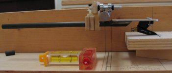
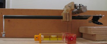
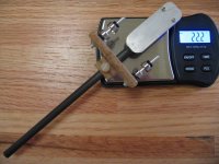
VTF 0 - SS pivot center to nominal stylus position set at 2 3/8" (hope that's the optimum?). The cutoff section of the wand at the left of the photo. Note the cartridge clips with solder blobs thereon. Careful viewers will note that there is no stylus seen - it got ripped out when setting up my customized Black Widow. "LPGear" replacement stylus puts the stylus at the exact end of the plastic 'nose'.
VTF 1 - Carriage balanced with a 1gm weight (venerable "Central Scientific Co. precision weights) at extreme end of wand. Total length of wand/headshell, end to 'stylus' is 7 7/8". Ortophon Super OM cartridge weight 4.6g.
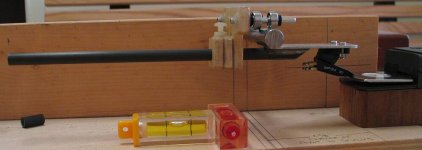
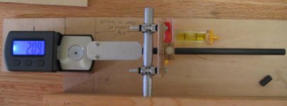
VTF 2 - Calibrated 0-5g digital scale, resolution 0.01g, set at the balance point of cartridge 'stylus.'
VTF 3 - WITHOUT ANY COUNTERWEIGHT the carriage/cartridge VTF is an average of 2.12g, deviations -0.06g to +0.08g . 15 successive measurements were made, dropping the carriage to the scale from ~1/8" height after it had zeroed. Here is the sequence (in grams): 2.10, 2.13, 2.10, 2.17, 2.10, 2.15, 2.18, 2.17, 2.14, 2.05, 2.07, 2.15, 2.04, 2.08, 2.10. As you can see I took the photo at 2.09g. This was 'good' since I reread the Ortophon 'optimum' weight specification, which was 1.5g (maximum 1.75g).
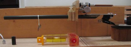
VTF 4 - WITH A PRECISION 0.5G COUNTERWEIGHT 20 measurements were made of the VTF, counterweight positioned as seen in photo on a piece of dental floss. Average of 1.47g VTF, with deviations of -0.05g to +0.06g. Measurements made as above, in grams: 1.51, 1.42, 1.49, 1.44, 1.43, 1.53, 1.43, 1.50, 1.45, 1.43, 1.51, 1.46, 1.45, 1.44, 1.47, 1.53, 1.45, 1.48, 1.46, 1.49.
Obviously with a +10g cartridge weight the counterweight will have to be increased in mass. With the same digital scale, measuring the Denon DL-160 on the customized Black Widow, the measured weight never varies more than 0.01g.
IMO the stability and reliability of VTF using the test fixture (a not so polished SS rod) isn't all that bad. Once the cartridge was affixed the system, rod and carriage, became somewhat reasonable in regards VTF. I make no claim for the absolute weights measured, but clearly I put some effort into measuring a horizontally-balanced system.
VTF 5 - THE MONEY SHOT, with a calibrated digital scale (resolution 0.1g). The complete carriage with cartridge affixed and cartridge clips in place, no wiring. The 0.5g counterweight is not measured in this photo, but let's add it in:
22.2g as measured.
+0.5g counterweight
------
22.7g total weight, with the Ortophon Super OM cartridge mounted and 0.5g counterweight.
Sadly, my 3-mounting point custom Teres kit turntable is going to require a movable mounting system for the DIY Linear Tracker assembly (if I'm to be able to use all three anticipated tonearms). I started work on that swing arm today ... maybe I'll polish my (SS) rod a bit more in the meantime. Hope the measurements and 'boy science' add to the majesty of it all? At least we now have some reference to 'stable and reliable' VTF measurements - with a SS rod and polished bearing edges. Caveat Emptor!
John
More research, with 5 photos to enhance the tedium. As I've noted previously the issue of VTF would seem to be more amenable to 'science' than 'art.' It is very clear that horizontal friction should be low, and that it is desired with this (these) designs that the vertical friction be somewhat higher.
I'd noted once I installed the Ortophon Super OM cartridge that the measured VTF with NO counterweight, during 5 sequential measurements clustered in the 1.37g to 1.41g range. Since there were going to be changes made to the Balsa Composite carriage I put further measurements off. When detailing the construction/weight issues last time I failed to note that the magnesium headshell had 3 coats of water-based polyurethane applied for corrosion resistance. No doubt a trivial addition of weight.
So, the wand has had about 1/2" cut off its end, the headshell has had its corners rounded for aesthetics, and the wand at the headshell end has been beveled to enhance cartridge clip clearance. In the full spirit of 'boy science' here's the photos explanations:
VTF 0 - SS pivot center to nominal stylus position set at 2 3/8" (hope that's the optimum?). The cutoff section of the wand at the left of the photo. Note the cartridge clips with solder blobs thereon. Careful viewers will note that there is no stylus seen - it got ripped out when setting up my customized Black Widow. "LPGear" replacement stylus puts the stylus at the exact end of the plastic 'nose'.
VTF 1 - Carriage balanced with a 1gm weight (venerable "Central Scientific Co. precision weights) at extreme end of wand. Total length of wand/headshell, end to 'stylus' is 7 7/8". Ortophon Super OM cartridge weight 4.6g.
VTF 2 - Calibrated 0-5g digital scale, resolution 0.01g, set at the balance point of cartridge 'stylus.'
VTF 3 - WITHOUT ANY COUNTERWEIGHT the carriage/cartridge VTF is an average of 2.12g, deviations -0.06g to +0.08g . 15 successive measurements were made, dropping the carriage to the scale from ~1/8" height after it had zeroed. Here is the sequence (in grams): 2.10, 2.13, 2.10, 2.17, 2.10, 2.15, 2.18, 2.17, 2.14, 2.05, 2.07, 2.15, 2.04, 2.08, 2.10. As you can see I took the photo at 2.09g. This was 'good' since I reread the Ortophon 'optimum' weight specification, which was 1.5g (maximum 1.75g).
VTF 4 - WITH A PRECISION 0.5G COUNTERWEIGHT 20 measurements were made of the VTF, counterweight positioned as seen in photo on a piece of dental floss. Average of 1.47g VTF, with deviations of -0.05g to +0.06g. Measurements made as above, in grams: 1.51, 1.42, 1.49, 1.44, 1.43, 1.53, 1.43, 1.50, 1.45, 1.43, 1.51, 1.46, 1.45, 1.44, 1.47, 1.53, 1.45, 1.48, 1.46, 1.49.
Obviously with a +10g cartridge weight the counterweight will have to be increased in mass. With the same digital scale, measuring the Denon DL-160 on the customized Black Widow, the measured weight never varies more than 0.01g.
IMO the stability and reliability of VTF using the test fixture (a not so polished SS rod) isn't all that bad. Once the cartridge was affixed the system, rod and carriage, became somewhat reasonable in regards VTF. I make no claim for the absolute weights measured, but clearly I put some effort into measuring a horizontally-balanced system.
VTF 5 - THE MONEY SHOT, with a calibrated digital scale (resolution 0.1g). The complete carriage with cartridge affixed and cartridge clips in place, no wiring. The 0.5g counterweight is not measured in this photo, but let's add it in:
22.2g as measured.
+0.5g counterweight
------
22.7g total weight, with the Ortophon Super OM cartridge mounted and 0.5g counterweight.
Sadly, my 3-mounting point custom Teres kit turntable is going to require a movable mounting system for the DIY Linear Tracker assembly (if I'm to be able to use all three anticipated tonearms). I started work on that swing arm today ... maybe I'll polish my (SS) rod a bit more in the meantime. Hope the measurements and 'boy science' add to the majesty of it all? At least we now have some reference to 'stable and reliable' VTF measurements - with a SS rod and polished bearing edges. Caveat Emptor!
John
Attachments
Before I read John's book (just kidding) I'd like to mention why Colin's 4 bearing rig is winning the race (get it, race, sorry). Any time one edge of the outer race is riding on the same plane as the opposite edge you will effectively have a solid axle which means there can be a difference in the speed on one side of the bearing to the other. Example is a single bearing inside a glass tube, or between two rods. A four bearing setup on a rod is like an independent suspension. And this is only for lateral motion. I can't imagine what is happening once vertical movement is added.
Even RR box cars with its solid axle wheels are flanged with a small radius for the same reason as they must go around curves. The outside rail is longer than the inside. If not for that difference in diameters the scrubbing action would be enormous.
The ideal, to me, is to have the bearing ride on the flat part of the outer race on a smooth round surface, but is going to be difficult to do, they keep falling off. A straddled vee configuration may work, but is difficult to build. My only criticism on 4 wheel tracking is that only three wheels can be moving perfectly at any one time. A true sprung suspension may be in order. Colin (I think it was him) was right again with leaving the axles to inner race a tad bit loose.
Zene
Zene,
Not sure what you mean by "only three wheels can be moving perfectly at any one time." The felt-tip marks I put on the outer races of the four bearings of my linear tracker seem to move all-together in lockstep when rolling on the rod. I'd been worried over the sage advice that I'd create divots and/or flats in the SS rod by polishing it. That didn't seem to happen (yet).
After I learned that I'd bought the 'wrong' ceramic bearings ($32) based upon earlier 'conjectures', I vowed to try to be 'clear and complete' in what I write, even if violated brevity protocol here - there's been a lot of revealed secrets in the past 100 or so pages. One sure has to pay 'reading dues' in these threads.
Then again, as a retired academic researcher type 'operational definitions' has become a sort of religious doctrine. Hey - remember the satellite that failed due to the use of english versus metric units (or vice versa, what was it)? Clarity requires rigor, and sadly, maybe too much text/photos. I'm glad this isn't a Twitter feed. Truly, I've been quite troubled by the 'just listen' VTF setting advice. I'm comforted by the reasonable 'slop' I find with setting VTF in my creation. It appears that with care in construction one can set VTF using a digital scale with some hope of getting in the ballpark.
Ad Astra,
John
John
John ... did read your long post, good stuff. Will print that one.
I look at most things micro rather than macro. A 1mm ball traveling the same rate of a record travels about 1/72 revolution per second (math critics welcome). That's not the same as rolling a bearing mount along a tube with your finger and checking turnover rate. Do I think the three wheel analogy is critical, certainly not, but getting to the nit picking analogies is certainly worth looking at, even for a second or two. If they have some validity they should be examined further, if not they can be disguarded permanently unless they come up again with other changes.
My favourite micro scenario is to be shrunk down and ride the stylus in the groove. Should be a trip.
Zene
Zene,
The bearing are far from being perfectly rigid, so as long as they are not grossly misaligned all four will make contact. secondly, being that they contact the tube at an angle, they center themselves and distribute the load to each pretty much equally. Again assuming that a they are not grossly misaligned.
The bearing are far from being perfectly rigid, so as long as they are not grossly misaligned all four will make contact. secondly, being that they contact the tube at an angle, they center themselves and distribute the load to each pretty much equally. Again assuming that a they are not grossly misaligned.
my guess and it is only that is that with four bearings each bearing is leveraged on an edge and what this does is to set tension to the internal rave assembly. The race does not have the ability to wobble in this configuration and stiffness in the assembly is what Bo called for and the four bearing system delivers that better. This is to me the same reason why rim drive sound better than belt drive turntables. With a rim drive the bearing assembly is biased into position. A belt drive TT can be made to function in the exact same fashion if the table is slightly tilted. I think the this same type of bias system can also be accomplished in a two bearing arm assembly. Just my take on this and I could very well be wrong but I hope that this may provide possible food for thought. Best regards Moray James.
Hello Moray
my guess and it is only that is that with four bearings each bearing is leveraged on an edge
I was initially intrigued by the two-bearing concept because of lower weight and cost etc.
After making a drawing of the two concepts, I tend to take the side of the four-bearing concept.
The top figure in the drawing shows the vertical pivot to be above the track rods which is not a good idea considering the fact that the vertical pivot is already too high.
The lower figure in the drawing shows the vertical pivot to be at the center of the track rod which is better.
I also showed the bearings in the lower figure in an exaggerated tilted position to illustrate how the bearings are preloaded in that design.
The only thing I would change in the four-bearing design is that, I would mount the track rods in one bearing at each end, which someone else suggested in this thread. If the track rods were glass tubes, the added inertia would be of no consequence.
Attachments
Last edited:
Ralf ... good drawings, mine are in Paint so never show anyone but my closest friends. I don't get my feelings hurt when they laugh.
You are right about a bearing in between two rods. I tried it and felt like a bowling ball rolling down the gutter. Cambering in can put the rougher part of the chamfer (if it has any) against the rod.
Seems better to use the chamfer to the face edge of the outer race where it should be somewhat smoother. That is done when the bearing rests at >30 < 45 degrees (the 1 to 1:30 clock positions).
Has anyone inquired into the linear bearing shown here? DIY turntable w/linear tracking tonearm - YouTube I cannot track it down.
If the LM4 linear is recip balls it's no better than my Thompson SPM08's and it's terrible. The LM4 that Kiirjbl uses in his videos DIY Linear Tracking Tonearm by kiirojbl 4 - YouTube used a DJ cart set at 3 grams. Not hardly what I would call hi-fi.
Zene
The bowling ball assessment is correct along with the higher vertical pivot, but that's not all with the two tubes. Lastly the main caveat is the fact it entirely dependant on the quality of bearing itself, whereas my shim setup actually allows for some slack in bearing quality, but sizing still seems to be important. The added weight of 4 bearings vs 2 is minimal, perhaps on the scale of 1 gram in reality. In all honesty, I've tried many ideas, every time I thought I had a better idea the 4 bearing design still won hence I stopped posting any new ideas since they were just backward steps thus far, this arm is the front end heart if my system, so much so my focus went back to the riaa stage and designing a Jfet input/current feedback phono stage. The results, outstanding!.
Colin
Colin
[Q
......
The only thing I would change in the four-bearing design is that, I would mount the track rods in one bearing at each end, which someone else suggested in this thread. If the track rods were glass tubes, the added inertia would be of no consequence.
After several readings of the sentence above I still don't understand it.
Track rods (plural)? The four-bearing design has only ONE track rod, or did I miss something?
Mount them in one bearing at each end? Why bearing(s), the track rods don't move, or did I miss something?
Added inertia? on something that does not move? or did I...
Maybe I completely misunderstand what the track rod(s) are. So please tell me.
Puzzled, Hansrudolf
this arm is the front end heart if my system,
so much so my focus went back to the riaa stage and designing a Jfet input/current feedback phono stage.
The results, outstanding!.
Colin
Colin,
Y`re make me curious.
")
Hans.
Hello Brumm
You got me there.
What I meant to write, was track rod, singular. During a warp, the tone arm carriage bearings would experience sliding friction which in my opinion is to be avoided. Mounting the track rod/glass tube in bearings, one at each end, would allow the tone arm and its carriage to follow a warp without the cartridge cantilever being pushed into the body of the cartridge. During a warp then, the tone arm, its carriage the four bearings and the track rod/glass tube would all rotate a degree plus or minus.
My reason for making reference to a track rod is that, not everyone in this thread is using a glass tube.
Sincerely,
Ralf
Track rods (plural)? The four-bearing design has only ONE track rod, or did I miss something?
Mount them in one bearing at each end? Why bearing(s), the track rods don't move, or did I miss something?
You got me there.
What I meant to write, was track rod, singular. During a warp, the tone arm carriage bearings would experience sliding friction which in my opinion is to be avoided. Mounting the track rod/glass tube in bearings, one at each end, would allow the tone arm and its carriage to follow a warp without the cartridge cantilever being pushed into the body of the cartridge. During a warp then, the tone arm, its carriage the four bearings and the track rod/glass tube would all rotate a degree plus or minus.
My reason for making reference to a track rod is that, not everyone in this thread is using a glass tube.
Sincerely,
Ralf
Hello Arch Stanton
Thank you for explaining it in simpler terms than I did.
Sincerely,
Ralf
When the disk is warped, the wand goes up and down and the four bearings slips around the glass tube.
If you support the tube with two bearings, the four bearings of the carriage don't slip, the tube rolls.
Thank you for explaining it in simpler terms than I did.
Sincerely,
Ralf
Hello tomatamot
I used the term track rod to mean glass tube because not everyone in this thread is using a glass tube.
Sorry for the confusion.
Sincerely,
Ralf
Hansrudolf,
Straight Tracker called the 2 bearings on the shimmed brass tube: Track rod!
You and I and maybe more say track rod to the Glass tube.
Am I wrong ?
Hans.
I used the term track rod to mean glass tube because not everyone in this thread is using a glass tube.
Sorry for the confusion.
Sincerely,
Ralf
Ok, thanks for the explanation. The big question is if the inertia of the rod (be it glass or whatever) and the bearings on its ends would not be larger than the friction of the bearings against the rod. Otherwise stated: would the arm, moving up and down, be able to turn the rod? It would need bearings with very low resistance I think.
It would be worth to make an experiment, imho. Anyone having a 4-bearing arm up for checking this?
Greetings, Hansrudolf
It would be worth to make an experiment, imho. Anyone having a 4-bearing arm up for checking this?
Greetings, Hansrudolf
- Home
- Source & Line
- Analogue Source
- DIY linear tonearm