Mike, your parallelogram lends itself to flexure pivot bearings. You would end up with fewer rattling balls.
That is a good idea. Korf did a series on these and tested a couple of different types.
Second Flexure Prototype
mistakes
Ruler and compass are better than freehand, to design; and CAD even better, because it allows to try the element's motion.
There are always problems to investigate, and solutions to apply (not to invent), it's only a matter of sweat. And these are only the first drops.
carlo
Ruler and compass are better than freehand, to design; and CAD even better, because it allows to try the element's motion.
There are always problems to investigate, and solutions to apply (not to invent), it's only a matter of sweat. And these are only the first drops.
carlo
Attachments
mistakes
Ruler and compass are better than freehand, to design; and CAD even better, because it allows to try the element's motion.
There are always problems to investigate, and solutions to apply (not to invent), it's only a matter of sweat. And these are only the first drops.
carlo
I like the idea of the carriage roller and pivot combined, but looks to me this can tip in Azimuth until you apply your next bit of great logic
Hello Mike56,
Here is a link to a manufacturer of flexural pivots: c-flex.com
I have been using them since 1982 when they were still made by Bendix.
However, they are expensive.
Sincerely,
Ralf
Many thanks Ralf, i don't have any experience but have had a look, they seem to have spring rate in rotation, is that correct please?
thanks, mike
Thanks Ralf, your appreciation is particularly welcome - I always try to design on the "what if " basis, even at the cost of mistakes, and someone's laughs; but with some unexplored results.
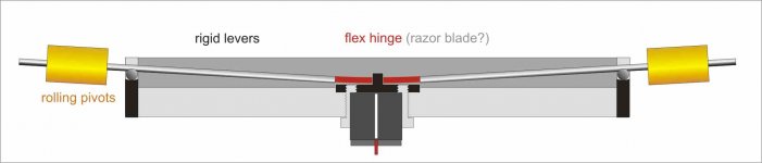
Knife blades - carrying the drawing on computer I saw that it didn't work: by turning downwards, the levers - tied to the center hinge - must move on the fulcrum, which can be obtained only by rolling on the support (to be calculated precisely).
levers horizontal at the max warp - in the middle on leveled groove; i think that a one direction rotation may be more consistent than an inversion.
Mike, I don't understand: the carriage moves horizontally on it's non recirculating balls. The cylinder, welded to the levers rolls on it's support just for vertical articulation The rotation on both sides is symmetric , so the azimuth should remain vertical.
carlo
Last edited:
Good morning carlo, sorry to confuse.
Horizontal, my note was really an additional idea to try and get two things for one, it was to use the same pivot for a carriage roller as for the vertical motion machine, whatever that is, that way it reduces bearing/pivot numbers and allows the small lateral motion needed for length change of the arms. it relates to a wheeled carriage, not a linear bearing type.
Vertical, i see the flex plate as being able to bend in various places along its length and so one side can move more than the other, i thought about it as two pivots one each side of the cartridge to confirm that in my mind, may well, of course, be wrong!
Best wishes to all
Mike
My first corkscrew carriage posted, worked with the same principle: the carriage wheels gave also the vertical movement. But letting ideas freeze, can be thought that this way the horizontal movement could also cause a vertical one. Not a good thing.
Stylus tip point of view
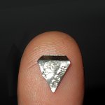
I had never posted this photo, not to discourage anyone: it is the hard lesson learned long ago from my Syrinx PLT (an "ambitious" project) total failure. This 100 mg is the force that may be exerted by the stylus to move an arm, at most 200mg, (a 5x5 square of office paper).
Now think again a flat hinge while folding (if it can)
ciao carlo
Stylus tip point of view
I had never posted this photo, not to discourage anyone: it is the hard lesson learned long ago from my Syrinx PLT (an "ambitious" project) total failure. This 100 mg is the force that may be exerted by the stylus to move an arm, at most 200mg, (a 5x5 square of office paper).
Now think again a flat hinge while folding (if it can)
ciao carlo
Attachments
mistakes
Ruler and compass are better than freehand, to design; and CAD even better, because it allows to try the element's motion.
There are always problems to investigate, and solutions to apply (not to invent), it's only a matter of sweat. And these are only the first drops.
carlo
What would prevent the rolling pivots from rolling earlier than the balls on which the whole gizmo rolls? The load is smaller on them.
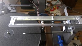
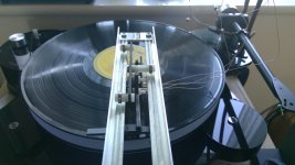
Well.....i completed the three wheel upgrade as per pic attached.
I have played just one side and it seems OK, the pitch motion and associated wow is apparently gone.
No detailed assessment yet because the change in geometry knocked on to the lift, which i did not foresee like several other things and i now need to fix that before trying more
mike
I have played just one side and it seems OK, the pitch motion and associated wow is apparently gone.
No detailed assessment yet because the change in geometry knocked on to the lift, which i did not foresee like several other things and i now need to fix that before trying more
mike
Attachments
Ciao Alighiszem, it' a long time: encouraging that you are interested.
Right observation, but I still don't know almost anything about this contraption, not even if it's worth a proto.
Being the two rolling pivot counteracting on the two opposite sides it should be stable, moreover the forces are acting separately and orthogonally, but who knows.
carlo
Right observation, but I still don't know almost anything about this contraption, not even if it's worth a proto.
Being the two rolling pivot counteracting on the two opposite sides it should be stable, moreover the forces are acting separately and orthogonally, but who knows.
carlo
Many thanks Ralf, i don't have any experience but have had a look, they seem to have spring rate in rotation, is that correct please?
thanks, mike
Hello Mike,
That is correct. They are made in plus & minus versions of 7, 15 and 30 degrees of rotation. If you think about it, there are many examples of partial rotation, hinges being one of them.
Sincerely,
Ralf
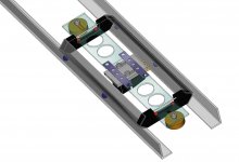
Corkscrew - radial rail
It doesn't seem so difficult to put together: anodized alu L profiles, Lexan levers, 4 + 4 balls (the red ones glued to levers and rolling on half pipe seats), S-steel hinges (maybe salvaged from disposable razors). Still to design the VTF fine tuning device.
In reality the balance between vert. vs hor. eff. mass, and the motion control of the compound (spring hinge + masses) will not be simple at all to achieve.
carlo
disclaimer: it's still just a sketch, not a project
Attachments
Hi Carlo, I've been following this and similar threads for a few years now. I rarely post, but wanted to say you have a very sleek design. I will call it a two carriage design: an outer carriage to allow the entire cartridge holding unit to follow the groove, and an inner carriage to allow the cartridge to move up and down to follow warps. I think your latest idea might have an issue with the inner carriage; it might try to also allow the cartridge to move with the groove of the LP.. I was thinking this could be eliminated with the addition of some coil springs that attach the inner carriage to the outer. Either that, or have some "z" shaped flat springs on either side of the cartridge that will attach to the sliding weighted rods on each side.. just some thoughts. I really like your ideas and your vision.
You're right popeetheus, the more I think about it, the more it resembles those old carriages in the wild west movies: big heavy carts, with a small seat on two thin crossbows, and the poor peasant wobbling above.
After all, warps are like bumps on a road. And we may think to vertical articulation like the suspension of a car (there is a lot to learn about).
However we have to use the least possible means not to dissipate those small forces. I'm hoping that those levers, acting orthogonally, would be almost not affected by the side force
carlo
springs are very difficult to handle, for a diyer
Corkscrew - radial rail
It doesn't seem so difficult to put together: anodized alu L profiles, Lexan levers, 4 + 4 balls (the red ones glued to levers and rolling on half pipe seats), S-steel hinges (maybe salvaged from disposable razors). Still to design the VTF fine tuning device.
In reality the balance between vert. vs hor. eff. mass, and the motion control of the compound (spring hinge + masses) will not be simple at all to achieve.
carlo
disclaimer: it's still just a sketch, not a project
I also like lots of this Carlo, having just got my Tricycle aligned to the rails, and that was difficult enough i like 3 point carriage main ride to avoid line up difficulties, maybe one side is one ball, the other 2? or perhaps this rail/carriage self aligns........?
BTW in the pic attached the carbon arm underneath is squint, it was a mod for cueing and it glued crooked, but no detriment in that, its not an illusion!
so this plays records, some good detail in places, sounds rock solid, good bass. biggest thing i notice is handling the carriage and the supports have microphony(? -is that the right word?) where my OL stuff has little - damping? also of course i am not yet "connected" to the platter spindle
Attachments
Great improvement, Mike.
On mine better a symmetrical friction on both sides, and just gravity for self centering, but I understand well that 3 bearings are better than 4.
Do a quick test, put a steel ball on a L profile, and try to hold it still: you will see that often a level is not enough. Then do the same test with a ball bearing cart. That's why I like non-recirculating: better there are only the sophisticated solutions developed by Niffy.
5000 years ago the Egyptians were already making very fast battle carts, with spoked wheels on greasy bearings, but to move the blocks of the pyramids they used non-recirculating: a matter of friction.
carlo
microphony: not clear what's happening. remember that CF is conductive
Last edited:
i notice is handling the carriage and the supports have microphony(? -is that the right word?) where my OL stuff has little - damping? also of course i am not yet "connected" to the platter spindle
This will be normal to some extent. My rail is damped to the point where if I tap it with a pencil I get a dull thud through the speakers. But I can hear when I move the carriage by hand on the rail.
If I were you I would damp the rail. If you used glass tube fill the tube with epoxy. I then epoxied carbon fibre between the rods and rail. My rail uses carbide rods. For your next rail you could use linear rails. I have a set of 6mm round linear rods I was going to use but went 4mm.
- Home
- Source & Line
- Analogue Source
- DIY linear tonearm