I am really not sure I understand what you are talking about. The cartridge only moves the small arm and cannot feel where it is relatively to the servo operated part. So how do you explain that it moves the double distance??
First the cartridge on the short arm moves on the record let's say 0.1 mm relative to the servo sledge, as you call is. Then the servo kicks in, corrects the error, and the servo sledge moves. This means, that he short arm moves backwards relative to the servo sledge. So 0.1 mm displacement of the stylus on the record needs two displacements of the short arm relative to the servo sledge - once forwards, once backwards.
alcohol
I am slowly building the Lil casey 3 (everything is unnecessarily complicated without a milling machine) and yesterday I was wondering what advantages there should be, since basically I am just changing the rail + carriage to avoid a tilting that is not even on my present version.
To console myself I have uncorked a good Barolo, and these are the consequences.
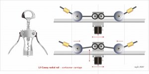
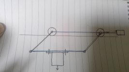
It's just a joke, but what if it would work? a fixed rail, with all the necessary weight, sophisticated jeweled carriage, to the garbage the parallelogram and all those damn complications.
But how great will be the friction of the 2 counteracting pulleys?
carlo
I am slowly building the Lil casey 3 (everything is unnecessarily complicated without a milling machine) and yesterday I was wondering what advantages there should be, since basically I am just changing the rail + carriage to avoid a tilting that is not even on my present version.
To console myself I have uncorked a good Barolo, and these are the consequences.
It's just a joke, but what if it would work? a fixed rail, with all the necessary weight, sophisticated jeweled carriage, to the garbage the parallelogram and all those damn complications.
But how great will be the friction of the 2 counteracting pulleys?
carlo
Attachments
Hi Carlo, i have been trying to pick up nuggetts from postings here for a while and have been given some excellent feedback. i have always liked the design and execution i have seen in your work as well, but was worried about the stylus arm movement in your previous warp clips, so i like what you are doing here, one worry is that there seems to be the possibility of cartridge rotation looking in this face on view, i wonder how mechanics or gravity can take that out? it needs to ensure even displacement of the two sides - two rails, one above the other is one idea, but your thinking is much better than mine, i don't have any Barolo, so cannot contribute more! - also my version of that corkscrew broke......mikealcohol
I am slowly building the Lil casey 3 (everything is unnecessarily complicated without a milling machine) and yesterday I was wondering what advantages there should be, since basically I am just changing the rail + carriage to avoid a tilting that is not even on my present version.
To console myself I have uncorked a good Barolo, and these are the consequences.
It's just a joke, but what if it would work? a fixed rail, with all the necessary weight, sophisticated jeweled carriage, to the garbage the parallelogram and all those damn complications.
But how great will be the friction of the 2 counteracting pulleys?
carlo
thanks for your words, Mike.
the two counter rotating pulleys are used to prevent rotation, with a vertical movement as in the corkscrew.
Now I'm wondering if a simple adjustable central spring, instead of the 2 CW, could be enough to avoid the pulleys.
But since there is no relative motion between the two pulleys, the friction should not be terrific - it will take me a coffee
addendum - of course to maintain horizontality the wheels are used in pairs, but with the same number of jewels
carlo
the warps video was unsatisfactory on the first LC , but the MK2 carbon video is not bad at all - even the versions of Walter's friends, in metal or with double rail (therefore heavier) do not complain about problems
Last edited:
So now i see this part, one wheel drives the other, these would be rubber or something to achieve this? - i like the idea of one of your parallelograms here achieving a more precise movement? - but in this case small and light.thanks for your words, Mike.
the two counter rotating pulleys are used to prevent rotation, with a vertical movement as in the corkscrew.
I don't grasp this point Carlo, could you kindly explain more for the less adept!?- of course to maintain horizontality the wheels are used in pairs, but with the same number of jewels
is there a link to these please?even the versions of Walter's friends, in metal or with double rail (therefore heavier) do not complain about problems
It's still just a joke, more a corkscrew than a LTA carriage.
It must travel on a horizontal plane, so with paired wheels with outer bearings, like a train.
Link - There are 3 or 4 nice variations, some time after the LC carbon posts. You'll find interesting photos and reviews.
c
It must travel on a horizontal plane, so with paired wheels with outer bearings, like a train.
Link - There are 3 or 4 nice variations, some time after the LC carbon posts. You'll find interesting photos and reviews.
c
It's still just a joke, more a corkscrew than a LTA carriage.
It must travel on a horizontal plane, so with paired wheels with outer bearings, like a train.
Link - There are 3 or 4 nice variations, some time after the LC carbon posts. You'll find interesting photos and reviews.
c
Carlo, as i struggle to understand a few of the details you've all become familiar with i as you have resolved things I am looking at your carriage ball bearings and whilst i understand that unless they slip they move in sync always, in practice do they ever slip and get out of sync, losing the extent of travel, balance etc? i don't see any restraint apart from the end stops.
thanks
Mike
I just realized, after a conversation with Carlo, that the main feature in the Lil Casey is not the fact that it dosen't change the angel to the platter when dealing with warps (after all this has been show to have very little consequence to the angel error between tip and RECORD) but it is to avoid the torque forces on the linear bearing. If the cartridge sits directly beneath the linear bearing, there will be no torque forces when the cantilever pushes the cartridge and the bearing.
Torque forces on a linear bearing will introduce extra friction.
A friend of carlo's says, if you run out of gas, you don't attache a 10-meter side pole to push your car.")
Torque forces on a linear bearing will introduce extra friction.
A friend of carlo's says, if you run out of gas, you don't attache a 10-meter side pole to push your car.
I just realized, after a conversation with Carlo, that the main feature in the Lil Casey is not the fact that it dosen't change the angel to the platter when dealing with warps (after all this has been show to have very little consequence to the angel error between tip and RECORD) but it is to avoid the torque forces on the linear bearing. If the cartridge sits directly beneath the linear bearing, there will be no torque forces when the cantilever pushes the cartridge and the bearing.
Torque forces on a linear bearing will introduce extra friction.
A friend of carlo's says, if you run out of gas, you don't attache a 10-meter side pole to push your car.
Interesting thoughts, as a newcomer to the thread but definitely interested to hear sound that is "better than any pivot arm, even the very good ones" i am intrigued to understand the key points.
I also see that there are several angles (!) on this, several of you have built different things that outperform your pivot arm experience........
So what are the key points (BTW, i will start at some point with a passive construction, maybe going on to experience a driven one later, why, simplicity on first build start up, i have no opinion on the preferred route.
1. Low mass, short arm that keeps any resonance way up in the >10khz region seems to be one
2. Very low carriage movement friction, both mobile and to get started (i think of this as limiting friction) - sufficient not to require the cartridge compliance to be challenged in any form of playback
3. A reasonably stiff connection between the arm and the record through the various interconnecting parts?
4. Some convenience factors about cueing and placing the records
What else, i would appreciate a summary of key points in order if any of you have the time please!
Thanks as always
mike
"words are not a designer tool"
told me, long ago, a teacher. So here are some attempts to answer to Mike's questions, that are the same i'm asking myself.
carlo
Computer drawing make even the roughest sketch look as a definite design, but this is just a way to focus the topic, in order to understand if there is a chance to design a working device
Attachments
Unfortunately my training was done when pencil and drawing pens ruled and i have never progressed to CAD, i also feel its difficult to sketch in CAD and your images show already that you are forced to think a bit deeper otherwise it doesn't appear complete, good news and bad in that! - meanwhile i always find precision gives others the idea one knows the answer or subject, How far is it to Rome, about 100 miles, - nobody believes you, 103.7 miles, everyone thinks you really know the answer!"words are not a designer tool"
told me, long ago, a teacher. So here are some attempts to answer to Mike's questions, that are the same i'm asking myself.
Computer drawing make even the roughest sketch look as a definite design, but this is just a way to focus the topic, in order to understand if there is a chance to design a working device
I like this direction, also adds to my few initial points, potential for keeping the stylus under the centre of friction of the carriage (mid point of the rails?) - so how about adding cueing to the paralell vertical motion and sufficient height to slide a record under if rotation of the whole arm(s) is preferred avoided?
but this is just a way to focus the topic, in order to understand if there is a chance to design a working device
Carlo, questions if i may!
Could you please explain the red rod?
Do you now prefer bevel wheels to your linear ball bearing aproach?
I see the friction wheels keeping things aligned vertically in V1, but how does the spring do that?
Mike
Surely, Mike.
the red cylinder is the central adjustable spring - instead of the 2 CWs - i've talked previously. There are tons of problems, maybe insurmountable, as you can understand from those two sketches (a pencil is enough for me too, but for the others I try to be clear as possible, sometime without success).
So no preferences, certainly not for a strange hypothesis vs an arm more or less working.
However, if you are thinking to build the best arm in the world at home, don't rely on me.
I like just experimenting every kind of TAs, with very conventional ideas about the qualities to achieve. A good advice to follow is to start with an Altmann or a Nanook 219 (it takes just a WE), and then a blind test, compared to your preferred one. Very useful
ciao carlo
I see the friction wheels keeping things aligned vertically in V1, but how does the spring do that?
Hoping that will part evenly on both sides the vert. force; honest springs sometimes behave this way
Hi Carlo, in the early '70's there was a unipivot arm design published in Hi Fi News or similar, i built that in the well equipped school workshop in the evenings and had it on one of the simple belt drive decks, it was pretty good back then and i had it until perhaps 1990........when i was doing other things, now i would like to build and compare a LTA with my Origin Live, when i do a project i like to think i have enough information to believe it will work well before i start, you gents have done loads, so hence collecting many peoples views on this thread, BTW, thanks for all those.Surely, Mike.
the red cylinder is the central adjustable spring - instead of the 2 CWs - i've talked previously. There are tons of problems, maybe insurmountable, as you can understand from those two sketches (a pencil is enough for me too, but for the others I try to be clear as possible, sometime without success).
So no preferences, certainly not for a strange hypothesis vs an arm more or less working.
However, if you are thinking to build the best arm in the world at home, don't rely on me.
I like just experimenting every kind of TAs, with very conventional ideas about the qualities to achieve. A good advice to follow is to start with an Altmann or a Nanook 219 (it takes just a WE), and then a blind test, compared to your preferred one. Very useful
ciao carlo
I see the friction wheels keeping things aligned vertically in V1, but how does the spring do that?
Hoping that will part evenly on both sides the vert. force; honest springs sometimes behave this way
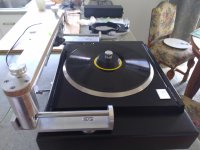
Spent the last week rebuilding the LTA and replacing the BOCA bearings with pin bearing wheels. I also extended the bridge rail 50mm beyond the rear of the plinth to make changing LP's easier and now I can remove the platter without having to remove the rail.
It still was not happy with the Stanton so I installed the Technics EPC205 which has a compliance similar to the Ortofon 2M Black. This combination seems happy to track an extremely warped LP. With the Stanton installed I could hear the distortion in each channel as the CL waggled back and forth.
The EPC205 sound amazing in this arm. Quiet passages are eerily silent. If I were to sum this up in a few words - Dynamic, Clarity, Detail and it sucks you into the music..........I love it
YouTube
YouTube
YouTube
Attachments
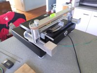
Spent the last week rebuilding the LTA and replacing the BOCA bearings with pin bearing wheels. I also extended the bridge rail 50mm beyond the rear of the plinth to make changing LP's easier and now I can remove the platter without having to remove the rail.
It still was not happy with the Stanton so I installed the Technics EPC205 which has a compliance similar to the Ortofon 2M Black. This combination seems happy to track an extremely warped LP. With the Stanton installed I could hear the distortion in each channel as the CL waggled back and forth.
The EPC205 sound amazing in this arm. Quiet passages are eerily silent. If I were to sum this up in a few words - Dynamic, Clarity, Detail and it sucks you into the music..........I love it
YouTube
YouTube
YouTube
It looks great! - do you feel its reduced friction of the pin bearing wheels that's brought this improvement, or something else? - i really like the idea of hearing eerily silent........so when you cue a track, just a click as the stylus touches down, no discernible hiss/rustle of typical vinyl noise?
Hoping that will part evenly on both sides the vert. force; honest springs sometimes behave this way
Or perhaps without springs, lightweight parallelogram on the vestigial carriage?? - apologies for poor quality of scribble attached...........i have obviously ignored lots because i don't have the knowledge and experience but it would satisfy all the criteria i have noted so far including stylus in line with carriage "wheels"
Attachments
Or perhaps without springs, lightweight parallelogram on the vestigial carriage?? - apologies for poor quality of scribble attached...........i have obviously ignored lots because i don't have the knowledge and experience but it would satisfy all the criteria i have noted so far including stylus in line with carriage "wheels"
I see what you are getting at. Might be a good solution. But you get a side thrust on the cantilever every time you are dealing with a warp. That could cause problems.
Warrjon:
The YouTube photos are great.
In all cases, your disc and TT are not concentric. To my eyes, the arm seems to be overshooting the groove centerline. I also can't tell if the overshoot is symmetric.
Exotic styli generally improve the groove fit in the tracing part, but the arm overshoot is a tougher task. Cart compliance and resonance damping are particularly difficult to match when separate components are used.
Some similar comments apply for vertical tracking/tracing.
All I can do is ask if you see the above overshoot. The questions, then, are (1) can you hear the difference, and if so (2) does it matter? Your personal assessment seems to be "yes" for both, but then it's hard to criticize your own child objectively.
My designs are of the pivoting variety that have very low & constant friction and generally skirt the above. In return, I must deal with tracking error and skating force issues. Everything has tradeoffs.
diyrayk & Straight Tracker have published straight-line tracking designs that compensate for overshoots using mechanical and electro-mechanical means. I would like to know if they can handle overshoot, and how well. Compensation, of course, is not a cure. It is slow, unlike electronic feedback, and is re-active, not pro-active. In the end, the same 2 questions apply. If correction is good enough, such artifacts as remain constitute a "don't care".
Andy
awolff761
Hi Andy,
I believe that the record Warren was using had the centre hole purposefully elongated in order to induce extreme eccentricity, a torture test. If you are going to get cantilever displacement you are more likely to see it on a record with extreme eccentricity. The cantilever displacement will be much less on a real world record than shown in the video.
Niffy
- Home
- Source & Line
- Analogue Source
- DIY linear tonearm