Very useful link, Hiten - thanks. All I know (too little) comes from my broken cartridges (few, but sometimes tonearm diying can be expensive) - always round section in a round seat, except in Shure that have a square tube (angled 45 °) with some elastomer cast inside.
And a vague memory of some Shure notes on the different characteristics that the elastomer should have at various frequencies, and for small vs large displacements: a damn complicated task, but of central importance for the "character" of a cartridge.
Niffy
may this be responsible for the other 10% in my AT95 test? a 0.5 mm shift of the contact point is about 10% of the stylus length.
Attachments
Last edited:
Lil Casey MK2 carbon - measurements
These tests repeat exactly those made for the Lil Casey MK1, with the same inverse pendulum rig and the same calculation procedures (# 2574 for photos and formulas ; # 2605 for results correction)
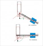
MK2 - horizontal movement
displacement S = 26 mm - theta angle = 4.26 ° - friction F = 1.63 mN
MK1 was S = 22 mm - theta angle = 3.6 ° - friction F = 1.41 mN
MK2 - vertical movement
displacement S = 32mm - theta angle = 5.24 ° - friction F = 2.01 mN
MK1 was S = 75mm - theta angle = 12.4 ° - friction F = 4.87 mN
The horizontal movement is a bit worse (carbon fibre is maybe softer than anodizing) but the vertical movement has less than half the frictions of before. Reducing weights was worth the effort.
Now vertical and horizontal frictions are very similar, and this explains the fluid and coherent behaviour seen with the macroscope, following easily even almost imperceptible eccentricities or warps like a gimbal TA (MK1 was ok on eccentricities, but faced small warps with the stylus bending).
This was my main target for a radial rail tonearm. But can it be still called a tonearm? there is no arm at all, just a moving carriage with both movements really parallel.
That's all - carlo
These tests repeat exactly those made for the Lil Casey MK1, with the same inverse pendulum rig and the same calculation procedures (# 2574 for photos and formulas ; # 2605 for results correction)
MK2 - horizontal movement
displacement S = 26 mm - theta angle = 4.26 ° - friction F = 1.63 mN
MK1 was S = 22 mm - theta angle = 3.6 ° - friction F = 1.41 mN
MK2 - vertical movement
displacement S = 32mm - theta angle = 5.24 ° - friction F = 2.01 mN
MK1 was S = 75mm - theta angle = 12.4 ° - friction F = 4.87 mN
The horizontal movement is a bit worse (carbon fibre is maybe softer than anodizing) but the vertical movement has less than half the frictions of before. Reducing weights was worth the effort.
Now vertical and horizontal frictions are very similar, and this explains the fluid and coherent behaviour seen with the macroscope, following easily even almost imperceptible eccentricities or warps like a gimbal TA (MK1 was ok on eccentricities, but faced small warps with the stylus bending).
This was my main target for a radial rail tonearm. But can it be still called a tonearm? there is no arm at all, just a moving carriage with both movements really parallel.
That's all - carlo
Last edited:
Now since the stylus moves in 45° direction for pure L or R signal, shouldn't be the horizontal and vertical compliance the same? Or should we consider the stereo signal as vector sum of monophonic (L+R, horizontal stylus movement) and spatial signal responsible for the stereo effect (L-R, vertical stylus movement)? In the latter case the difference in hor and vert compliances could cause narrowing or widening the stereo field.
Or not, because the stylus follows the shape of the groove in either case. Perhaps the intention was to move the horizontal and vertical resonance frequencies apart from each other, maybe in accordance to the difference of the excitation signal in the two different planes.
Hi Icsaszar,
It would seem logical to have the compliance and the effective mass the same in both the vertical and lateral planes if we just consider the stylus as moving at 45°. It is better as you suggest to look at the stereo signal as a vector sum. The product of the cartridge compliance and effective mass determines how much the cartridge body will move relative to the neutral axis of the groove. The ideal solution would result in zero relative movement. Due to physical limitations this is not possible. The aim is to select a combination of compliance and mass that will result in the smallest relative movement. Of course the arm also has to be able to track warps and eccentricity whilst keeping the cartridge aligned with the groove. The compliance and mass will result in a resonant system. It is important to ensure that the resultant resonant frequency is above frequency of warps and eccentricity and below the audio band.
The graph below shows the amount that the cartridge body will move relative to the movement of the stylus. The blue trace shows an arm/cartridge tuned to the recommended 10hz. The orange trace is for an arm tuned to 5hz. The black vertical line is at 0.55hz, the rotational frequency of 33 1/3rpm, and represents the frequency of eccentricity. It is also the lowest frequency at which warps occur. The red vertical line represents the highest frequency at which warps occur. Warps at this frequency will be at a very low amplitude.

For the purpose of this graph I have assumed that compliance is constant at all frequency. If the compliance were to decrease with frequency, like with the audio technica, the slope above resonance would be shallower meaning that there would be greater relative cartridge body movement. If the compliance increases with frequency, as I believe the ortofon and goldring do, the slope would be steeper resulting in less cartridge movement. This seems like a better option to me.
The blue trace has its resonant peek safely above the highest frequency of warps and below the audio band.
The orange trace has its resonant peek within the range effected by warps. If the vertical tuning was set to this frequency then warps could cause excessive vertical movement of the cartridge. The resonant peek is however still a long way above the frequency at which eccentricity occurs. At the frequency of eccentricity neither trace is noticeably above the 0dB line meaning there is very little relative movement. The orange 5hz line is slightly higher but is still very low. The really big difference is above resonance in the audio band. The movement of the cartridge body is over 12dB lower with the orange 5hz tuned arm. This is particularly important at very low frequency. At 20hz the blue 10hz tuned arm is only at -10dB whereas the orange 5hz tuned arm is at nearly -24dB.
In my arm I purposely tuned the lateral resonant frequency to be much lower than the vertical. The actual frequencies are slightly different to the ones shown here. As warps only occur vertically it does not matter that the lateral resonance is within the range effected by them, it is still way above the frequency of eccentricity. This means that the cartridge body will move a lot less laterally in the audio band than if tuned to the same frequency as the vertical. Mono signals are modulated purely laterally with no vertical component. In order to prevent the stylus from being thrown out of the groove by excess vertical motion low frequencies, below about 120hz, are cut only in mono. By tuning the lateral resonance to a lower frequency results in much lower movement of the cartridge body.
To illustrate this more clearly the following graph shows how much the cartridge body actually moves relative to the stylus with a 20hz sine wave. Again this graph assumes that compliance is constant with frequency.

Above resonance the movement of the cartridge body is out of phase with the movement of the stylus meaning that they are actually moving in the opposite direction to each other. (At resonance the cartridge body will be at -90° to the stylus) This means that the deflection of cantilever will be greater than if the cartridge body was stationary. This can adversely effect tracking so minimising excess motion is desirable.
As you can see the motion of the arm tuned to 5hz is much lower than that of the arm tuned to 10hz, about 4 times lower. The motion of the 10hz tuned arm is really quite large. It does not matter if your speakers do not have significant output at 20kz. If the groove is modulated with very low frequency the cartridge body will move at this frequency. If playing a note in the midrange would you prefer the cartridge body to be stationery or waggling about at low frequency. Of course you would prefer the cartridge body to be as stationery as possible.
As you increase in frequency the difference in cartridge movement between the 5hz and 10hz tuning remains at about 12dB. The absolute difference between the two does however decrease dramatically as the frequency increases. The next two graphs show the relative movement of the cartridge to the stylus with 50hz and 100hz signals.


The difference between the two become almost indistinguishable from the motion of the stylus by the time you get to 100hz. At this frequency the motion of the cartridge body due to the compliance/mass effect is almost zero. (Other factors like bending mode resonance and compression waves will still cause relative motion but these are not effected by the tuning of the arm). So by the time you get to frequencies where there is stereo information, above 120hz, the motion of the arm is essentially the same vertically and laterally.
There are definite benefits to making the lateral compliance and effective mass higher than the vertical especially in the reproduction of bass frequencies. Reducing lateral motion of the cartridge at low frequencies by lowering the resonant frequency has benefits across the entire audio range.
Niffy
Last edited:
Hi Carlo,
"may this be responsible for the other 10% in my AT95 test? a 0.5 mm shift of the contact point is about 10% of the stylus length."
I would say probably not. The deflection you point out would effectively lengthen the cantilever which would therefore have a greater lever effect. If anything this would increase compliance not reduce it. I think it is much more likely that the manufacturers make the vertical compliance lower than the lateral on purpose.
Congratulations on the substantial decrease in vertical friction and effective mass. The big question is how does the mkii sound in comparison to the mki? The total elimination of the armtube and all the nasties that come with it has got to be one of the main goals of tonearm design.
Niffy
Thanks for the appreciation, Niffy: is just an experiment that someone had to do, sooner or later.
How does it sound? Since I've never been able to distinguish silver cables from those of my electrician or the capacitor brand on a tube amp, I'm careful not to talk about sound, or draw conclusions from my impressions. Here in Italy we all think ourselves as great gourmets, but once (for work, a convention of a large winery, our client for advertising) I witnessed a real blind test with professional sommeliers: after the laughs I am still ashamed for them, they did not distinguish a cabernet from a barolo.
So I just observe that it traces easily, better than the few commercial or diy linear ones I could see, and sounds clearly, without chattering or strange resonances (very little needle talk perceptible on the rail with the stethoscope, less than in MK1). But sounds different from my references (as did the Rabbit too) - Is this an advantage? as audiophiles say, perhaps a long running-in is needed, a practice that can bring you to consider even fried grasshoppers a delight.
I consider this arm as a successful experiment, in the sense that it works avoiding some obvious problems, but it is still a linear one, therefore an arm that does not use a favorable long lever to overcome the frictions on the articulations and the twisting of the cables.
Could it improve? of course, if I were a manufacturer I could have a poltruded rail made with a section that avoids every possible tilting of the carriage (now you have to waste some time at the beginning to set it's small CW correctly) or sturdy jewel bearings of minimum weight and size: but fortunately I am only a diyer doing this for amusing, not to earn my life. Therefore satisfied to have reduced everything to the essential in only two steps.
carlo
I would like to understand your graphics better: how are composed the movements induced by the defects of the disk (which are measured in mm) and those of tracking (a few tens of microns)?
Last edited:
I think it is much more likely that the manufacturers make the vertical compliance lower than the lateral on purpose.
Quote, your (and my) measurements on different cartridges, say this; however it is strange not to find a physical structure that justifies it. It would be very easy to make an elastomer with a rectangular or elliptical section to differentiate the two compliances, while it seems unlikely to inject two different elastomers into a so small element. In my cartridges (but also on those seen on web) I see just round, or rhomboid sections, or others, but always symmetrical. MC types use a single piano wire, 360° simmetric by definition.
As you have shown, a different hor. and vert. compliance could be useful for the resonance of the arm, but what would happen while tracking? being always complex movements in every direction how to predict their behavior in an inhomogeneous structure? how to avoid distortions?
Different sound - not to be misunderstood, I'm not saying that these arms sound worse or better, only that after 50 years of listening with pivoted ones you learn to compare them, to understand their strengths and weaknesses, while you remain a little surprised with the bare and essential sound of these.
It reminds me the difference between hearing a string quartet playing inside a theater or a church, or into the rehearsal room.
carlo
Found the Shure article quoted in a previous post
High Fidelity Phonograph Cartridge - Technical Seminar | Knowledge Base | Shure Americas
This instead was among my stored articles, completely forgotten (age's advantages ") )
)
Yet another way to measure arm/cartridge resonance... - John Elison - Vinyl Asylum
really interesting - and more the following ones on damping influences
c.
)Yet another way to measure arm/cartridge resonance... - John Elison - Vinyl Asylum
really interesting - and more the following ones on damping influences
c.
Hi Carlo,
All four graphs show relative movement of the cartridge body compared to stylus movement.
The first graph is a log-log plot. 0dB in this graph means that the cartridge body is moving the same amount as the stylus. - 20dB means the cartridge body is moving 1/10th the amount the stylus is. A 6dB difference is equivalent to an absolute difference of double so -6dB of 1mm results in 0.5mm of movement and -6dB of 1micron is 500um. The final three graphs are each at a set frequency and have a linear vertical scale. Again these show the ratio of groove modulation/stylus movement to cartridge body movement. I have added the overall motion of the cartridge relative to the stylus on these three.
I hope this answers your question.
Niffy
Hi Niffy,
The graphs are a bit mystifying to me- you added “the overall motion” - help!
In my quest for understanding, I revisited this doc
http://www.cartchunk.org/audiotopics/ToneArmMechanics.pdf
It has a nice calculation of effective mass, (page 9) among others- curiousm if it can pass the muster
Best
Coolerooney
Hi, is anyone out there? no new tonearms/techs?
So let's talk about cables, the most useless topic in hifi history. But not for us, unfortunately with linear trackers the cables are a mechanical component of such importance to impede even a correct functioning.
On the net you can see photos of passive linears with heavy carriages using plasticized cables, compressed air tubes, or even "rotating" head shells able to flex a few cm of 4 common cables: but how the hell do they do?
In my pendulum test even a thin cable (2 twisted pair of 3 x 0.12 mm enameled tx wire) was enough to double the friction of the carriage, so in the final wiring I reduced them to just 2 x 0.08 mm. But the cable loop is still able to push-pull the carriage, when lifted: bad cables or too good carriage?
Strange paradox: the better the carriage the more important become the mechanical properties of the cables. With a bad cart instead the cables do not count almost nothing, because it does not move ... No good, imho
Has anyone analyzed this matter, are there solutions? Difficult to further reduce the cable section.
carlo
Diyer's small satisfaction: I've found a video of a famous passive where finally can be seen the stylus on the eccentricity, and compared it with my LilCasey: it is not too bad to have the SF in axis, and a 16 gr carriage, cartridge included
To Carlo. I would completely agree as to tonearm cables. My own experience confirms crucial importance of mechanical properties of cables. I've tried several times to start discussing that issue here, with no substancial results. Audiophiles prefer to stick with pure electrical, or even esoteric cable properties, and I don't now why...
Walter: these cables work fine, the carriage tracks effortlessly and I don't hear any alteration of the sound. But I trust my ears much less than of a reasoning. (this is why I am not interested in the silvery sound of silver cables vs the asphyxiated noise of oxygen-free ones)
This: if the cables can push my carriage (1.6mN friction) it means that they exert a bigger force. This force is relevant, and variable too (the loop is practically a spring that extends and contracts): seems enough to worry about.
carlo
This: if the cables can push my carriage (1.6mN friction) it means that they exert a bigger force. This force is relevant, and variable too (the loop is practically a spring that extends and contracts): seems enough to worry about.
carlo
No, unfortunately - the counterproductive effects of such solutions (to overcome the carriage friction) have already been discussed and demonstrated in this thread.
Here the problem is more sneaky: the cable loop behaves like a spring (flexing) + two torsion bars (twisting), applying a variable side force to one channel or the other, depending on how it is positioned.
His strength can be even higher than the friction of a good cart (<< 2,0 mN), to which it is added or subtracted.
A simple test can be more convincing than this explication in my bad english
carlo
There is one very drastic solution, that can eliminate the drag from the wires completely:Hi, is anyone out there? no new tonearms/techs?
So let's talk about cables, the most useless topic in hifi history. But not for us, unfortunately with linear trackers the cables are a mechanical component of such importance to impede even a correct functioning.
On the net you can see photos of passive linears with heavy carriages using plasticized cables, compressed air tubes, or even "rotating" head shells able to flex a few cm of 4 common cables: but how the hell do they do?
In my pendulum test even a thin cable (2 twisted pair of 3 x 0.12 mm enameled tx wire) was enough to double the friction of the carriage, so in the final wiring I reduced them to just 2 x 0.08 mm. But the cable loop is still able to push-pull the carriage, when lifted: bad cables or too good carriage?
Strange paradox: the better the carriage the more important become the mechanical properties of the cables. With a bad cart instead the cables do not count almost nothing, because it does not move ... No good, imho
Has anyone analyzed this matter, are there solutions? Difficult to further reduce the cable section.
carlo
Diyer's small satisfaction: I've found a video of a famous passive where finally can be seen the stylus on the eccentricity, and compared it with my LilCasey: it is not too bad to have the SF in axis, and a 16 gr carriage, cartridge included
Make a servo controlled sledge (just like a servo controlled tonearm) to carry the wires.
This is not just for fun, I feel this is the ultimate solution, and perhaps not that difficult to get functioning. Perhaps salvage an existing linear srve tracker?
or a wi fi cartridge, even simpler ... ;-)
c
My suggestion is no joke.
After making the best possible passive linear tracking arm, why not support it with a servo sledge, to carry the wires (and air hose, if it is an air bearing)?
My suggestion is no joke.
After making the best possible passive linear tracking arm, why not support it with a servo sledge, to carry the wires (and air hose, if it is an air bearing)?
Yes. I thought about it when I was building my air bearing arm. But after building many different versions of air bearing arms, I don't think it is necessary. It complicates things with no or very little benefits. In order to eliminate wire or air tubing drag, you need to do it in both lateral and vertical planes. An active sledge can reduce horizontal drag only. But it may introduce vibration and noise, etc.
Last edited:
- Home
- Source & Line
- Analogue Source
- DIY linear tonearm