I have spotted a bit of a problem with my idea of using the counterbalance spring to tune the compliance of the system.
Quick recap. The model I used had a vertical effective mass of 100g with the spring attached at half the length of the levers. Using a 667N/m spring and a 15um/mN cartridge would give a vertical resonance of 10hz.
The problem is this. Under gravity the downward force exerted by the rail etc is about 1N and as I made the spring attachment half the length of the levers the tension on the spring would be 2N. The spring would therefore be extended by only 3mm. If the cartridge has to raise by 1mm to navigate a warp the spring would have to shorten by 0.5mm. This would reduce the tension on the spring by 0.33N and would mean that the mass supported by the spring would only be about 83g. The other 17g would have to be supported by the cartridge. If the tracking force was originally 2g then it would increase to 15g at the top of a 1mm warp. As problems go that's a bit of a biggie. I'm going to continue to play with this idea to see if it is possible to use attain a non-varying tracking force whilst simultaneously lowering overall system compliance.
Niffy
Last edited:
As problems go that's a bit of a biggie.
Niffy, this convinces me much more than the results of the spreadsheet (eff mass = 4.2). Imputing a mass zero for the spring seems to me too simplistic. Another method for calculations is needed, imho
The recipe remains the usual: short lever, counterweight as close as possible to the fulcrum - and that's the mod to the parallelogram. The other is to reduce moving weights (hor and vert) to the limit, and beyond
Fortunately the test (with a huge mass of 70 gr) does not behave very differently from normal: maybe in warps more than the height counts the slope, ie the vertical acceleration. With severe warps even the lighter arms do not prevent the stylus bending to bear the stress.
carlo
Last edited:
Niffy, solution isn't complicated, based on plane geometry and physics, those you know better, than me. With my pivot spring arm there still is about 0,5 gramm difference of VTF between high and low on 1,5 mm warp, which I easily can reduce even more.
Attachments
Last edited:
Interesting solution, Walter; you mentioned it in a post, but now it's really clearer.
Is the spring used in that position for the greater linearity due the longer length? From the point of view of the forces does not seem favorable.
Second question: does anyone know the formulas to calculate these two kind of pendulums? (period - potential energy - effective mass). The first looks like a physical pendulum (or compound, how do you call?) but the second? nothing found on web
carlo
Attachments
NOCD, In my arm, on warped records, while climbing up, VTF increases. If on plane record VTF is 1, 5 gr. , on the top of 1,5mm warp it is about 2gr. I can improve it further, and even tried to use king of tackle block (polyspast) for that purpose, which appeared to be a bad idea. Difference of leverage momentum should be enough.
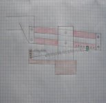
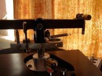
The longer the spring, the less VTF varies. The less leverage a spring has as to a pivot point, the less VTF varies. Using proper leverage, it is possible to reach miniscule length of spring contraction-extension, and so, minimal variation of VTF. Long spring, positioned horizontally, closer to the pivot point serves that purpose well.
A good source of different springs to scavenge, are older, purely mechanically controlled cassette decks.
It can be seen on my picture, that there are multiple holes on both ends of spring attachments, to choose variable leverage.
Last edited:
Walter, I was trying to understand the differences between your measures and Niffy's model: if the large increase in the VTF calculated by Niffy could be compensated by the inclination of the spring in your arm but, as you say, it is not so.
I'm checking how to apply (extremized) it in the parallelogram, but in it still does not convince me.
Thanks for these hints - carlo
I'm checking how to apply (extremized) it in the parallelogram, but in it still does not convince me.
Thanks for these hints - carlo
Attachments
Last edited:
NOCD, you are on a right track. Almost all of your variants from two last posts are close to aim. IMO, we may consider, as acceptable , if VTF varies 10%-20% while stylus climbing 2mm warps. On a good record it will be considerably less.
As to polyspast, it appeared as unnecessarily complicated solution, with additional friction and time delay. Proper leverage will do it alone. We don't need a belt fed pocket pistol, are we?
As to polyspast, it appeared as unnecessarily complicated solution, with additional friction and time delay. Proper leverage will do it alone. We don't need a belt fed pocket pistol, are we?
Last edited:
No, only the second. #2448
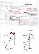
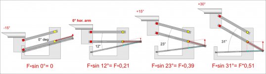
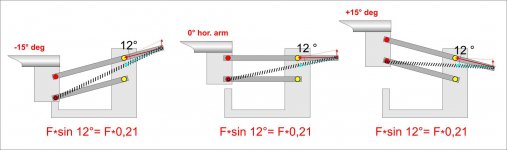
See the forces breakdown in the first one #2447: at -15 ° there is completely no balance (zero spring force), while at + 15 ° it goes up to 40%. Relevant variation and, furthermore, the sin alfa function is sinusoidal, non-linear.
The second one may work very well, weight always balanced in every position. At least on lamps (a Luxo seats on my table since 40 years),
But there are even cons:
1 - the spring exerts on the bearings a force of 5 times of which must balance; and if the lever is half of the other, for a mass (rail + cart + cartridge) = 50 gr is doubled to a 5N - Huge spring.
2 - getting the right spring: it's true what you say about decks, but I love my Teac C2X, and I'll never hurt it, because it still sounds great, playing memories of the past. I am scavenging Amazon and RS: many measures except useful data (strength).
Anyway it seems promising and I want to go deeper: part making stopped.
carlo

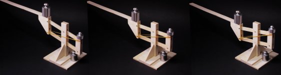
No. just 4 (#2435 #2440) are too much for my taste.
That was only the wooden mock up of the parallelogram: being sensible to 1/2 gr good for quick check. What is difficult is to calculate and find the right spring.
Here the rubber band was too weak and + 20 grams were needed to balance 100 gr.
carlo
That was only the wooden mock up of the parallelogram: being sensible to 1/2 gr good for quick check. What is difficult is to calculate and find the right spring.
Here the rubber band was too weak and + 20 grams were needed to balance 100 gr.
carlo
6 bearings indeed?
Most pivot arms typically have 4 bearings anyway.
Hi all, long time stalker - first time poster
i've been brewing a tonearm in my head for a while and hopefully you all have a few pointers on what im thinking...
so, looking at building a:
-carbon tube arm, no set length yet (either 12mm OD to work with rod ends below, or headshell fitting into end OR 10mm OD with a DIY headshell)
-RC drone motor mount (aliexpress special) for arm to LM8LUU bearing mount
-LM8LUU linear bearing - with seals & lube removed
-8mm S/S rod
-either a RC drone motor mount rod-end as a headshell, or use an off-the-shelf one.
-undecided on counterweights yet
thats the guts of if, but a few questions:
- does the arm need to be perpendicular to the track? ie is it better to have it perpendicular or angled to the track (still linear travel, just angled) ie perpendicular seems it would track worse (possible bearing play/bind) than angled, where the bearing assembly is effectively being 'pulled' along the rail
- has anyone used the linear bearings?
- how much play does the wiring need at the TT base (thinking they'll be centred on the track travel)
im basing this on me making an altmann DIY TT
Thanks!!
does the arm need to be perpendicular to the track? ie is it better to have it perpendicular or angled to the track (still linear travel, just angled) ie perpendicular seems it would track worse (possible bearing play/bind) than angled, where the bearing assembly is effectively being 'pulled' along the rail
- has anyone used the linear bearings?
- how much play does the wiring need at the TT base (thinking they'll be centred on the track travel)
im basing this on me making an altmann DIY TT
Thanks!!
Hello MKDnz,
I don't think it makes a difference as to whether the tone arm tube is situated perpendicular to the track or not. The stylus however should be located as close to the carriage as possible.
All tone arms are always PUSHED across the LP, never pulled.
I would never use linear bearings, because dust and dirt particles on the track will work their way into the bearing.
Dressing the wiring gets a little more difficult. I think you may have to determine that experimentally. Generally I would say that, the wires should descend toward the tone arm from a point higher up. Also, when the tone arm carriage moves back and forth, the wires are stressed. That stress could be bending stress or torsional stress. I would dress the wires such that they are stressed in torsion. The concept is simple but may take a sketch to clarify.
A simple sketch on your part would help us understand your ideas a little better.
Sincerely,
Ralf
thanks for that Ralf, good info
i meant it as the bearing being pulled 'behind' the tonearm rather than it being 'pushed' in front depending on arm angle off perpendicular. like you say it probably wont make too much difference but will try both.
i lightened (and cheapened) the arm fixing idea to o'rings looped onto the bearing housing VS the rc drone motor mount clamp but may try both options - ill try sketch something up.
wiring i can hang via a top mount hook or similar and lay it so that the torsion movement is the relief like you say.
id still like to try the linear bearing idea, im wary of dirt buildup too but its only the one linear bearing vs multiple roller bearings in other designs ive seen, so theoretically less to go wrong/less to clean. im going for a clean, simple aesthetic so the less parts the better.
this is the drone motor mount idea for arm mount onto bearing (bearing mounted in clamps) Carbon fiber 2208/2212/2213 motor mounting seat holder 16mm tube clamps pipe clip for DIY quadcopter multicopter drone accessory-in Parts & Accessories from Toys & Hobbies on Aliexpress.com | Alibaba Group
thanks for that Ralf, good info
id still like to try the linear bearing idea, im wary of dirt buildup too but its only the one linear bearing vs multiple roller bearings in other designs ive seen, so theoretically less to go wrong/less to clean. im going for a clean, simple aesthetic so the less parts the better.
[/url]
It is not a matter of how many parts, but it is all about friction. I am not sure what kind of linear bearing you are talking about. As I know, most of linear bearings are NOT going to work for linear arms because linear bearing have way too much of moving mass and way too high friction.
- Home
- Source & Line
- Analogue Source
- DIY linear tonearm