Just an idea for an air bearing turntable and I'm someone already thought of it. Can you use two airbearings? A spherical air bearing working as the thrust plate holding the ball and an air bearing bushing for the female part? This is probably simpler than a concoction of the Vanden Hul The Point One turntable without the magnet. The issue would be how the spherical bearing can handle the load.
Just thinking out loud...
Just thinking out loud...
Air bearing turntable
Hi all,
An full air bearing will give very low fiction, almost zero, and should have disappearingly low rumble. The motor and motor controller will have to be chosen taking this into consideration. Many motors require a certain load in order to maintain speed stability. An assynchronus motor requires a high level of drag so would be unsuitable. A quality dc motor with a competent controller should work well.
A full air bearing will have no physical connection between the platter and the rest of the deck, apart from the drive belt (or idler wheel) and stylus. The contact point in a more conventional bearing act as a mechanical grounding point which helps to dissipate energy created by the stylus modulation in the record groove. Without this point the platter will have to be able to control/dissipate all of this energy by itself. This tends to require a massive platter, which the bearing Jim found could definitely handle.
My question is, do you think that adding a damping system, say a silicon fluid bath with a fin attached to the bottom of the platter, would be beneficial? It would simultaneously load the motor and help to damping the platter. Not at all dissimilar to the damping trough on Jim's arm.
Niffy
Sorry for keeping us off topic with my last post.
Back on topic. I've bitten the bullet and ordered some sapphire vees and tungsten carbide pivots. They have worked out considerably more expensive than I had expected, £150 all in. Ouch.
I certainly hope that they make a positive impact.
Niffy
Back on topic. I've bitten the bullet and ordered some sapphire vees and tungsten carbide pivots. They have worked out considerably more expensive than I had expected, £150 all in. Ouch.
I certainly hope that they make a positive impact.
Niffy
Sorry for keeping us off topic with my last post.
Back on topic. I've bitten the bullet and ordered some sapphire vees and tungsten carbide pivots. They have worked out considerably more expensive than I had expected, £150 all in. Ouch.
I certainly hope that they make a positive impact.
Niffy
Source?
Source?
I shopped around. I purchased the pivots from true point in the UK at £18+vat each. For this design I need 4 pivots and 4 vees. True point didn't have ideally sized vees and the closest size that they did have were over £20+vat each. Fortunately small parts, via Amazon in the US, had exactly the correct size at £50 Inc vat and postage for 5 of them. These are manufactured by Swiss jewel company. I checked out their website and they appear to be top quality. Unfortunately they don't seem to supply in the quantities I required. Small parts did have some cobalt steel pivots but the tip radius of these were way too small. I find it really weird that neither distributor had both components in matching sizes when you can't use one without the other.
Niffy
Last edited:
"True point didn't have ideally sized vees and the closest size that they did have were over £20+vat each"
Hi Niffy,
Would these do the job?
10 Balance ***** Jewels Rubys Watch Parts Steampunk Vintage Movements Old Pocket | eBay
or these:
http://www.ebay.com/itm/FULL-tube-o...804293?hash=item2ed4083905:g:NcEAAOSwEK9Twp7g
Hi Niffy,
Would these do the job?
10 Balance ***** Jewels Rubys Watch Parts Steampunk Vintage Movements Old Pocket | eBay
or these:
http://www.ebay.com/itm/FULL-tube-o...804293?hash=item2ed4083905:g:NcEAAOSwEK9Twp7g
Last edited:
Cheers Consty,
The second of the two listings you've found looks very interesting. The chances of getting a set of suitable jewels from that selection are probably reasonably high.
I might just order a tube for something to experiment with. Finding suitable pivots seems to be the hardest part. Nearly a hundred pounds for the ones I ended up ordering but they are highly polished, dimensionally accurate and tungsten carbide. It's going to be difficult to find better.
Thanks for the discovery
Niffy
Hi Niffy,
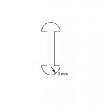
For your arm’s rail, I have a suggestion. Please see the drawing. If the edge of the wheel is 2 mm in radius. Then, even if the wheel swings front and back, its parameter with the rail will not change. And, VTF won’t change either although VTF may not change too much on your existing wheels.
Jim
Hi Jim,
After you made this suggestion and I replied I have been thinking more deeply into this approach. I may have replied too hastily.
When using ball race bearings I aimed to keep the contact angle between the edge of the bearing and the rods low, about 20°, as this helps to minimize lateral friction. As vertical movement is accommodated by the play in the bearings the effect of this low angle on vertical friction is not an issue.
With the pin bearings all of the vertical movement is accommodated by the wheels sliding on the rods. Keeping the contact angle low in this approach has the negative impact of increasing vertical friction. In order to keep the vertical friction as low as possible without negativity effecting the lateral friction too much I have increasing the contact angle to 40-45°. In your suggested configuration the contact angle would be 30°. By reducing the width of the wheels to about 2mm the contact angle would increase to about 42°. This would alleviate both of the problems that I proposed. The increase in wheel mass would be much smaller, 0.6g per wheel, and the vertical friction would be much the same as it was with the 1.5mm thick wheels with 0.15mm radius edges.
I have crunched some numbers and came to a compromise design that uses 1.5mm thick wheels with a larger 0.5mm radius edges. This will maintain the same wheel mass. The contact angle is almost exactly 45°. This should have almost identical lateral friction to my previous design but may help to reduce vertical friction by as much as 15%. By increasing the wheel edge radius the area of the contact points between wheel and rods will have increased and in doing so will have reduced contact pressure. Whether this is beneficial I am unsure.
I have made these wheels and fitted them to my arm. It is only a small physical change and may have had an effect on sound quality but any change is so small it is difficult to be certain.
Thanks for your input. Any further insights or suggestions are always welcome.
Niffy
Hi Niffy,
I am glad it helped.
In order to reduce the mass of wheels, you may make the wheels as my drawing. I know you have access to a lathe so it is not a problem to make such wheel. I always wish I could have this kind of machinery. However, yours is only 1.5 mm thick, I don’t think it will make too much difference though.
Speaking of sonic effect, I think it won’t make too much difference. It is all about better controlling the behavior of the carriage.
I recently acquired a lot of air bushings from eBay. There are four 1”s, four 1.5”s and four 2”s at very reasonable price. I am very excited. I may use 1” bushing to make another arm since I have enough material left.
To my experience, it is a big improvement from 1/2” bushing to 3/4” busing for a moving bearing tonearm. I expect 1” bushing can be even better and at least as good as 3/4” bushing.
I am thinking to make a full carbon fiber carriage as yours. My question for you is if you used any glue, such as epoxy adhesive, to make your carriage. I am not sure the sonic effect of epoxy adhesive. I assume it should not degrade the sound because carbon fibers contain epoxy itself. I also plan to glue the carriage directly on the air bushing in order to reduce mass and increase rigidity. 1" bushing weights 83 grams already.
Jim
Attachments
Last edited:
Hi Jim,
Unfortunately I do not actually own a lathe. This makes the manufacture of components such as the wheels and axles a complete PITA. It took about 4hrs to make the latest set of wheels. I recently acquired some diamond lapping compound and have finished the new wheels to 0.5micron surface. This does seem beneficial, the surface is so smooth it is difficult to grip the wheels enough to pick them up. The wheels do seem to roll slightly more smoothly. I have not measured the actual lateral friction as yet as the only rail that I have for use with these wheels is already fitted to the deck.
There is no problem in using epoxy to glue carbon fibre, it is in fact ideal. My arm is built around a balsa wood core that is light weight and offers excellent damping. Premade pre-preg sheets of carbon fibre tend to have woven outer lamina with several unidirectional fibre lamina alternating at 0° and 90° (dependent upon the number of lamina). If you can get a custom lay-up. It is best to align the outer woven lamina at 45° and have the inner lamina at 0°. This increases both longitudinal and torsional rigidity. This is what I had made. It costs a bit more but is worth it. I'm quite well versed in this material, I have a degree in composite engineering.
The 1" air bearing will probably be torsionally stiffer than the smaller sizes which should be advantageous. The only possible downside is that the vertical pivot axis will need to be higher which may result in increased warp wow and tracking force variation. As you have excellent record clamping this is unlikely to be problematic.
Niffy
Hi Niffy,
Wow, you have a degree in composite engineering. You are the perfect person I cab ask. You should make a tonearm as SAT’s.
I thought to make a custom carbon fiber part for the carriage, but after watching some of video on line, I think it is too complicated for me. It involves a lot work and needs some experience too. So, I decided to glue 3 mm carbon fiber plate together. I happen to have some already. Any brand of epoxy do you recommend?
I had experience with JB Weld clear weld. It is pretty strong stuff.
Thank you!
Jim
Hi Jim.
Avoid generic epoxy as these are poor quality. My favourite is araldite. The products from loctite and evostick are also very good. The precision or 24hr cure type are slightly better than the rapid cure variety. To get the best bond roughen the surface of the carbon fibre with coarse sandpaper then clean to remove any dust. Apply adhesive sparingly to both surfaces and firmly clamp. Leave any excess adhesive until it has cured past the gel stage and has the consistency of a soft plastic. It can now be trimmed with a sharp knife. To get the best bond place the clamped workpiece into an oven. Set the temperature to 70°C/160°F. Allow the temperature to stabilize and leave for at least 5hrs for precision adhesive and for rapid adhesive leave for 40minutes to 1hour. Allow the oven to completely cool before removing the clamps. Heat curing increases bond strength by 2-3times and allows you to move onto the next step in construction sooner. The difference between precision and rapid adhesive that have been heat cured is negligible.
Niffy
Niffy,
I have a question for you.
I am going to order a piece of 3/8” carbon fiber sheet to make the all carbon fiber carriage. I also found a water jet cutting service to cut the small pieces for me. After gluing the pieces together, I may sand the carriage to the shape I like. What kind of coating should I apply on the sanded surface? How about a thin layer of epoxy?
Thank you!
Jim
Niffy,
I have a question for you.
I am going to order a piece of 3/8” carbon fiber sheet to make the all carbon fiber carriage. I also found a water jet cutting service to cut the small pieces for me. After gluing the pieces together, I may sand the carriage to the shape I like. What kind of coating should I apply on the sanded surface? How about a thin layer of epoxy?
Thank you!
Jim
Hi Jim,
Sorry to take a while to reply, I missed the new message notification.
I assume that you are planning on making a solid carbon fibre carriage based on the thickness of the sheet you mentioned. Was this for use with air bearing arm?
Water jet is a great thing if available and can give a surprisingly good finish. Thicker carbon fibre sheets normally have a good finish on both sides so only the cut sides should require further finishing.
You can use a thin layer of epoxy to finish the surface but this can prove very difficult. It is very difficult to get a smooth finish just by spreading epoxy over a surface. The epoxy would need to be sanded then polished. Managing to completely smooth the surface without sanding through as some points, especially the edges, is nigh on impossible. If the surfaces are flat or only curved in one plane and the structure is a simple shape another method is possible. Spread the epoxy evenly over a surface then press and smooth a piece of thin polyethylene sheet onto the surface squeezing out as mush epoxy as possible. Allow the epoxy to cure then peel the polyethylene of, the epoxy should have a nice smooth finish. My local record store uses tough carrier bags that I have used very successfully for this application. Of course test this approach before trying it on a finished piece. You will probably have to do one surface at a time so it is time consuming.
I have also used automotive clear lacquer a couple of times. One attempt worked beautifully the other not so well. So testing first is still a good idea.
Carbon fibre is not normally used in solid pieces as its main advantage is weight reduction. Structures are normally hollow to maximize this advantage. For instance a 12mm OD tube with a 1mm wall has the same flexural rigidity as a 10mm solid rod of the same material yet the tube has less than half the mass. My arm uses carbon fibre that is only 0.75mm thick on balsa cores to make panels. These panels form a box section into which the other components of the arm sit. Also Carbon/balsa has really nice self-damping.
Have you performed any calculations to estimate effective mass? For vertical effective mass this can be a pain but is worth doing.
Niffy
Hi Niffy,
Thanks for replying!
The all carbon fiber carriage I am planing to make is for 1” Newway air bearing linear tonearm. Please see the drawing. So far, it is just a rough drawing. I may try to make it a bit nice looking.
No. I haven’t done any calculation of vertical and horizontal mass yet. In fact, I am not sure how to do it. I guess they should be almost same since the air bearing is frictionless vertically and horizontally.
My main goal for the all carbon fiber carriage is to make it as simple and rigid as possible. I have the feeling that the carriage can be too light if it is all carbon fiber. Therefore, I already thought about how to add some mass to the carriage. I have some 2 mm thick lead sheet left. If needed, I may add some mass to the bearing by covering the bearing with lead sheet.
Jim
Attachments
Hi Jim,
The drawing of your proposed carriage looks great. Pretty much an H beam and should be extremely rigid, especially if fabricated from 3/8 carbon fibre. I would suggest making the rear section, that supports the counterweight, in a similar fashion to the front.
Increased mass can have beneficial effects. Depending upon your cartridges compliance there will be an ideal mass for the entire carriage. I believe that every gram of this mass should be used in a way that improves the rigidity and damping characteristics of the carriage. I call this total mass the mass budget and aim to spend every fraction of a gram in the most economical way. Adding lead will increase mass and damping but will not add rigidity. Thick sections of carbon fibre in the small sizes your drawing suggests they will have excellent self damped. Increased rigidity results in higher resonant frequency. Higher frequencies are easier to damp. Your proposed design should require no additional damping material.
The lateral effective mass is the mass of the entire carriage including cartridge and counterweight. If I recall correctly your cartridge has a compliance of 15um/mN. I reckon a total mass budget of between 70g and 140g covers the ideal range. This gives a lateral cantilever resonance of 5hz to 3.5hz.
The vertical effective mass will not be the same as the vertical and should be much lower than the lateral. Again for your cartridge, and taking into account your excellent record clamping system, I would aim for 17g to 26g. This will give a vertical cantilever resonance of 10hz to 8hz. This is lower than the normal recommended range as you have pretty much eliminated record warps. I have explained how to work out vertical effective mass in Kevinr's souther arm on a thorens thread which I believe you have posted in. I can repost it here if that is better for you.
Happy building.
Niffy
Ps my tungsten carbide pivots turned up today and hopefully I'll be able to start making the bit required to fit them soon.
My bad. I think it was a different thread specifically about effective mass. If you want more info on effective mass please feel free to ask.
Niffy
If Jim isnt interested in more info on vertical effective mass I'm sure a lot of others....like myself..... reading along would.
Thanks!
- Home
- Source & Line
- Analogue Source
- DIY linear tonearm