Dear all,
I have just finished reading all this thread (198 pages, 1980 comments!).
It was an excellent source of extremely valuable information.
I have already successfully built an air bearing type tonearm I have used for about one year. It worked fine but I wanted something new... And this is how I found this thread.
My initial design goal was a pair of U shaped bearings riding on a stainless steel rod, but I've learned reading this thread (among may other things) that 4 POC are better than 2 and glass is better than SS")
I have one question though: has anyone thought of (or even better, tried) a pair of V shaped bearings riding on a single glass rod?
This would keep the 4 POC concept in place and would use a single glass rod instead of two, making good use of the KISS principle mentioned extensively in this thread
I have just finished reading all this thread (198 pages, 1980 comments!).
It was an excellent source of extremely valuable information.
I have already successfully built an air bearing type tonearm I have used for about one year. It worked fine but I wanted something new... And this is how I found this thread.
My initial design goal was a pair of U shaped bearings riding on a stainless steel rod, but I've learned reading this thread (among may other things) that 4 POC are better than 2 and glass is better than SS
I have one question though: has anyone thought of (or even better, tried) a pair of V shaped bearings riding on a single glass rod?
This would keep the 4 POC concept in place and would use a single glass rod instead of two, making good use of the KISS principle mentioned extensively in this thread
Attachments

Dear all,
I have just finished reading all this thread (198 pages, 1980 comments!).
It was an excellent source of extremely valuable information.
I have already successfully built an air bearing type tonearm I have used for about one year. It worked fine but I wanted something new... And this is how I found this thread.
My initial design goal was a pair of U shaped bearings riding on a stainless steel rod, but I've learned reading this thread (among may other things) that 4 POC are better than 2 and glass is better than SS
I have one question though: has anyone thought of (or even better, tried) a pair of V shaped bearings riding on a single glass rod?
This would keep the 4 POC concept in place and would use a single glass rod instead of two, making good use of the KISS principle mentioned extensively in this thread
I think it works, but you need to add some kind of protecting mechanism to prevent the cartridge dropping off the glass rail. Most of linear tonearms here don’t have this kind of mechanism, therefore, I used C type glass rail. The ball bearings move inside of glass tubing.
There are no doubts in my mind that 2 points of contact is better than 4 points of contact. Any 4 points of contact tonearms will cause VTF changing while the needle travels. I have been thinking this for a while, here is the proposal which may work. I can’t tell for sure if it works fine or not unless I actually build one. However, I don’t think I will build one in the foresee future with two air bearing tonearms in my hand.
Attachments
Last edited:
The only commercially available tonearm using the silicone damping trough trick that I know of is the Rock 7 from Townshend. But please note that according to them, the submerged paddle must be placed as close as possible to the cartridge in order to get the full bass improvement expected. Of course, you'll easily notice this is not the most record changer friendly solution...
Attachments
Last edited:
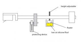
Townshen’s is for pivot tonearm. Mine is for linear tonearm. They are different although mine has damping function as well. Mine also provides third supporting point for the arm. So, with two supporting points from the v-groove bearings, it forms a triangle to keep the arm balanced. Damping is secondary because the paddle floats on the surface of silicone fluid and doesn’t sink in the silicone fluid. The third supporting point may also reduce the fiction of bearing since it may reduce the mass of arm.
Last edited:
But wait a minute... Wouldn't the floater pose a huge rise in VTF for each "hill" in a warped record? Remember what Archimedes said about the force pushing upwards an object submerged in a liquid... With a floater, it is not only the viscosity of the fluid that matters but mostly its density!
Hi consty, Hi Jim,
Recently I have been heavily involved in developing a better mechanical bearing design. As part of this I built a rig to measure actual lateral friction on which I have tested many different configurations. The best couple of these have been fitted to my arm and listen to. So far this experimentation is looking very positive and improvements in sound quality over the dual rod two bearing design has been achieved. I have built and tested both of the designs you have suggested. When testing I take hundreds of separate measurements and plot the distribution. This reveals a lot about the behaviour of the bearings but to try and keep this post reasonably short I'll just present the mean coefficient of friction for each type tested.
My new design is reverting to the use of pin bearings, similar to those used in clocks are watches, and am therefore not using the ball race type bearings. These are, I admit, considerably more effort to make and set up. Theoretically pin bearings should have several advantages. They should have lower friction than ball race bearings. As they have no loose unloaded balls bearings chatter will be eliminated. The carriage will be supported on what are essentially four spikes, similar to those used in speakers and equipment isolation supports, leading to ideal mechanical grounding. The pin bearings I am currently using are really basic. The pins are made from sewing pins with the ends rounded and polished. The vee cups are made from stainless grub screws with the cups punched and polished. Once the best wheel/rail configuration has been determined these will be replaced with tungsten carbide pivots and sapphire vee jewels.
The test rig has the bearings set the same distance apart as in my arm carriage with the load appied at the same location relative to these as the stylus in order to give as realistic a result as possible.
As a baseline I have measured the friction of two different types of ball race bearings on a dual rod rail.
The first tested were full ceramic zirconium oxide. These had a mean lateral coefficient of friction of 0.01. The other bearings were Boca silicon nitride hybrid. These had a mean coefficient of friction of 0.006, a 40% improvement. Both types are almost certainly better than the standard grade used by most contributors to this thread but as I haven't actually tested all types this is conjecture. The Boca bearings definitely had the edge on sound quality.
The design suggested by super is a knife edge design. This design should have minimum vertical friction so a damping system as shown in the diagram is needed. Bo Hannson moved away from using knife edge design in the cantus in order to increase vertical friction which acts to damp the arm, making the damping trough unnecessary. Using a knife edge design with ball race bearings has another disadvantage. With the dual rod ball race design the vertical pivoting of the arm is accommodated by the play in the ball race, the vertical pivot is aligned with the lowest balls. With the knife edge you have a second pivot where the wheels touch the rail. Having two different pivot points is unstable. I tested a knife edge design with pin bearings so I only had a single vertical pivot. The mean lateral coefficient of friction with this design was 0.0097, not as good as the best ball race bearings. I did not pursue this design further so cannot comment on sound quality.
I also tested the design as suggested by consty. Again this used my pin bearings. The rail was a single 4mm glass rod. The wheels were 15mm in diameter with a 140° V groove and 3mm thick. The shallow V was selected to minimize friction. This design resulted in a marked reduction in lateral friction with a coefficient of friction of 0.0051. The vertical friction was, however, noticeably higher than the ball race type. I have not built a rig to measure actual vertical friction but a simple pendulum test shows that it is about three times as much. When testing this design I used my spare dual rod rail and just ran the wheels on top of one of the rods, saved me having to make another rail just for this test. My dual rod rail uses two 4mm rods which are separated by a 1.5mm spacer.
Whilst testing this design I inadvertently knocked the wheels so that they ran in between the rods, similar to how the ball race bearings run. I immediately noticed that the test carriage seemed to run more smoothly so I retested with the wheels in this location. The lateral coefficient of friction dropped to 0.0044 and the vertical friction dropped by a similar amount. A serendipitous discovery. These wheels were made of aluminium. Using a harder material for the wheels should decrease rolling resistance so next I made another set of wheels from stainless steel (316) and tested these. The friction dropped again quite dramatically to 0.0035. The vertical friction also dropped slightly but was still notably higher than with the ball race bearings.
I built a new rail to accommodate these new wheels and fitted them to my arm and sat down to listen. Remember that they were still using my crude home made bearings. The improvement in sound quality was subtle but immediately noticeable. The separation between individual instruments improved giving a greater sense of air. Fine detail improved as did what many call prat (pace rhythm and timing). However the high vertical friction did cause some issues. So next I built another rail but this time with the 4mm glass rods touching and new wheels, again from stainless steel but now only 1.5mm thick. These tested the same in lateral friction, 0.0035, but had half the vertical friction (confirmed by theory and testing).
These new wheels resolved the vertical tracking issues and the sound seemed to take another small step forward.
In my opinion the improvements in sound quality are mainly due to the elimination of bearing chatter, though improved grounding and reduced lateral tracking error due to friction will play their part.
My experimentation is on going. The addition of quality pivots and sapphire vees will almost certainly help. I have also been given some tungsten carbide rods by fellow diyaudio member hottattoo that I am very excited to experiment with. The extreme hardness of this material should reduce rolling resistance further. Thanks hottattoo.
My experiments do suggest that the current dual rod rail design is actually superior to either the knife edge design as suggested by super or the V groove wheels as suggested by consty.
Here are a couple of photos showing the current setup.


Niffy
Recently I have been heavily involved in developing a better mechanical bearing design. As part of this I built a rig to measure actual lateral friction on which I have tested many different configurations. The best couple of these have been fitted to my arm and listen to. So far this experimentation is looking very positive and improvements in sound quality over the dual rod two bearing design has been achieved. I have built and tested both of the designs you have suggested. When testing I take hundreds of separate measurements and plot the distribution. This reveals a lot about the behaviour of the bearings but to try and keep this post reasonably short I'll just present the mean coefficient of friction for each type tested.
My new design is reverting to the use of pin bearings, similar to those used in clocks are watches, and am therefore not using the ball race type bearings. These are, I admit, considerably more effort to make and set up. Theoretically pin bearings should have several advantages. They should have lower friction than ball race bearings. As they have no loose unloaded balls bearings chatter will be eliminated. The carriage will be supported on what are essentially four spikes, similar to those used in speakers and equipment isolation supports, leading to ideal mechanical grounding. The pin bearings I am currently using are really basic. The pins are made from sewing pins with the ends rounded and polished. The vee cups are made from stainless grub screws with the cups punched and polished. Once the best wheel/rail configuration has been determined these will be replaced with tungsten carbide pivots and sapphire vee jewels.
The test rig has the bearings set the same distance apart as in my arm carriage with the load appied at the same location relative to these as the stylus in order to give as realistic a result as possible.
As a baseline I have measured the friction of two different types of ball race bearings on a dual rod rail.
The first tested were full ceramic zirconium oxide. These had a mean lateral coefficient of friction of 0.01. The other bearings were Boca silicon nitride hybrid. These had a mean coefficient of friction of 0.006, a 40% improvement. Both types are almost certainly better than the standard grade used by most contributors to this thread but as I haven't actually tested all types this is conjecture. The Boca bearings definitely had the edge on sound quality.
The design suggested by super is a knife edge design. This design should have minimum vertical friction so a damping system as shown in the diagram is needed. Bo Hannson moved away from using knife edge design in the cantus in order to increase vertical friction which acts to damp the arm, making the damping trough unnecessary. Using a knife edge design with ball race bearings has another disadvantage. With the dual rod ball race design the vertical pivoting of the arm is accommodated by the play in the ball race, the vertical pivot is aligned with the lowest balls. With the knife edge you have a second pivot where the wheels touch the rail. Having two different pivot points is unstable. I tested a knife edge design with pin bearings so I only had a single vertical pivot. The mean lateral coefficient of friction with this design was 0.0097, not as good as the best ball race bearings. I did not pursue this design further so cannot comment on sound quality.
I also tested the design as suggested by consty. Again this used my pin bearings. The rail was a single 4mm glass rod. The wheels were 15mm in diameter with a 140° V groove and 3mm thick. The shallow V was selected to minimize friction. This design resulted in a marked reduction in lateral friction with a coefficient of friction of 0.0051. The vertical friction was, however, noticeably higher than the ball race type. I have not built a rig to measure actual vertical friction but a simple pendulum test shows that it is about three times as much. When testing this design I used my spare dual rod rail and just ran the wheels on top of one of the rods, saved me having to make another rail just for this test. My dual rod rail uses two 4mm rods which are separated by a 1.5mm spacer.
Whilst testing this design I inadvertently knocked the wheels so that they ran in between the rods, similar to how the ball race bearings run. I immediately noticed that the test carriage seemed to run more smoothly so I retested with the wheels in this location. The lateral coefficient of friction dropped to 0.0044 and the vertical friction dropped by a similar amount. A serendipitous discovery. These wheels were made of aluminium. Using a harder material for the wheels should decrease rolling resistance so next I made another set of wheels from stainless steel (316) and tested these. The friction dropped again quite dramatically to 0.0035. The vertical friction also dropped slightly but was still notably higher than with the ball race bearings.
I built a new rail to accommodate these new wheels and fitted them to my arm and sat down to listen. Remember that they were still using my crude home made bearings. The improvement in sound quality was subtle but immediately noticeable. The separation between individual instruments improved giving a greater sense of air. Fine detail improved as did what many call prat (pace rhythm and timing). However the high vertical friction did cause some issues. So next I built another rail but this time with the 4mm glass rods touching and new wheels, again from stainless steel but now only 1.5mm thick. These tested the same in lateral friction, 0.0035, but had half the vertical friction (confirmed by theory and testing).
These new wheels resolved the vertical tracking issues and the sound seemed to take another small step forward.
In my opinion the improvements in sound quality are mainly due to the elimination of bearing chatter, though improved grounding and reduced lateral tracking error due to friction will play their part.
My experimentation is on going. The addition of quality pivots and sapphire vees will almost certainly help. I have also been given some tungsten carbide rods by fellow diyaudio member hottattoo that I am very excited to experiment with. The extreme hardness of this material should reduce rolling resistance further. Thanks hottattoo.
My experiments do suggest that the current dual rod rail design is actually superior to either the knife edge design as suggested by super or the V groove wheels as suggested by consty.
Here are a couple of photos showing the current setup.
Niffy
Hi Niffy,
Thanks for this extensive comment. Like usual, lots of useful info!
Your carbon fiber bat-tonearm in the middle of a stainless steel jungle never ceases amazing me. It certainly looks (and most probably sounds) like a 6 digits priced TT (if not probably better).
Thanks for this extensive comment. Like usual, lots of useful info!
Your carbon fiber bat-tonearm in the middle of a stainless steel jungle
never ceases amazing me. It certainly looks (and most probably sounds) like a 6 digits priced TT (if not probably better).Hi Niffy,
Thanks for this extensive comment. Like usual, lots of useful info!
Your carbon fiber bat-tonearm in the middle of a stainless steel jungle
Cheers Consty,
I don't know if I'd go as far as 6 digits, definitely 5. The cost to build is 4 digits so value for money is right up there. The design was all about sound quality, sound quality, sound quality. I think the deck does look absolutely stunning but this was largely luck. The best sounding shapes just happened to be the best looking, then more luck that all the sizes of the different bits gelled so well aesthetically. I'm a rubbish photographer so none of my pictures do it justice. I might be a tiny bit biased but I think it is both the best looking and more importantly the best sounding deck I have seen or heard.
Niffy
Hi Niffy,
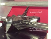
First, I am trying to understand the construction of your tonearm. Please see the attached photo. So, the wheel moves in between two rods. From the picture, it seems to me that the wheel has v-groove. Correct me if I am wrong.
Speaking of my proposal, if I understand it correctly, Bo Hannson’s so called knife edge means that the edge of outer ring of a ball bearing touches the glass rail. It will generate damping. I don’t know if he did same design as my proposal. But, I don’t believe his proposition personally. Clear Audio uses convex ball bearing. Convex ball bearing can generate damping, too. You don’t need a regular flat outer ring bearing to produce damping. In the meantime, a flat outer ring bearing will change VTF. Convex ball bearing may change VTF, too, but not as much as flat outer ring bearing.
In your knife edge rail and v-groove wheel test, what kind of rail you used? I think the rail should be stainless steel or carbide blade. I think the friction will be reduce greatly.
Jim
Attachments
I have followed this thread, for quite a while. And would like to throw out a variant for any thoughts.
What about a single concave bearing, contact point. Then, with the use of two "outriggers". These would make contact with the the viscous trough
One concave bearing can't guide the needle moving in precision straight line.
Hi Jim,
I've knocked up a diagram on my computer this morning but could not get it to convert to a format suitable for posting on this site so I gave up and photographed the screen, sorry for the low quality of the image.

As you can see there is no V in the wheel. The edges are radiused slightly, about 0.15mm.
I have tried the knife edge design several times in slightly varying styles and all seemed to have the same problem of excessive lateral friction. The knife edges were stainless steel in all cases. One of things that is important in a knife edge design is not to make the edge too sharp as this causes the contact pressure to be very high, exceeding the elastic limit of the materials used resulting in binding. The wheels also work better if the groove in the wheel is a V rather than a U shape. The small radius of the knifes edge then has two contact point, one on each side of the V. If the radius of the knife edge is small the distance between the contact points will be very small. My current design is in a fashion a knife edge design. Instead of the knife edge being the rail the edge is the wheel is and the V is formed between the two rods that make up the rail. My current wheels are similar to a large radius knife edge but with the excess material removed leaving only the portion that actually contact the rail. The effective radius of my current knife edge is 1mm. This may seem quite large but the amount the wheel has to slide over the rods is still very small. For the arm to pivot by 1° requires the contact points to move by only 0.015mm, that equates to a record warp of 1mm. With my record clamping system that's about 5 times as much as I ever see. As the movement is so small variations in tracking force will be insignificant, less than 0.5% (rough calculation)
In a way my design is half way between your proposal and that of Consty. The main difference being that in my design the V is the rail instead of the wheels.
One idea that I am contemplating is to use rods that are 2mm diameter for the rail and make the wheels 0.8-1mm thick. This will reduce vertical friction by 40-50% whilst keeping lateral friction about the same. Basically moving closer to a true knife edge. One thing I have to be careful of in this approach is not to make the wheels too narrow (knife edge too sharp) as this causes the lateral friction to increase. I think that an equivalent to a 0.5mm radius edge is probably the limit.
I hope this clarifies things. Any insights or ideas on how to further develop this idea are of course always welcome.
Niffy
I've knocked up a diagram on my computer this morning but could not get it to convert to a format suitable for posting on this site so I gave up and photographed the screen, sorry for the low quality of the image.
As you can see there is no V in the wheel. The edges are radiused slightly, about 0.15mm.
I have tried the knife edge design several times in slightly varying styles and all seemed to have the same problem of excessive lateral friction. The knife edges were stainless steel in all cases. One of things that is important in a knife edge design is not to make the edge too sharp as this causes the contact pressure to be very high, exceeding the elastic limit of the materials used resulting in binding. The wheels also work better if the groove in the wheel is a V rather than a U shape. The small radius of the knifes edge then has two contact point, one on each side of the V. If the radius of the knife edge is small the distance between the contact points will be very small. My current design is in a fashion a knife edge design. Instead of the knife edge being the rail the edge is the wheel is and the V is formed between the two rods that make up the rail. My current wheels are similar to a large radius knife edge but with the excess material removed leaving only the portion that actually contact the rail. The effective radius of my current knife edge is 1mm. This may seem quite large but the amount the wheel has to slide over the rods is still very small. For the arm to pivot by 1° requires the contact points to move by only 0.015mm, that equates to a record warp of 1mm. With my record clamping system that's about 5 times as much as I ever see. As the movement is so small variations in tracking force will be insignificant, less than 0.5% (rough calculation)
In a way my design is half way between your proposal and that of Consty. The main difference being that in my design the V is the rail instead of the wheels.
One idea that I am contemplating is to use rods that are 2mm diameter for the rail and make the wheels 0.8-1mm thick. This will reduce vertical friction by 40-50% whilst keeping lateral friction about the same. Basically moving closer to a true knife edge. One thing I have to be careful of in this approach is not to make the wheels too narrow (knife edge too sharp) as this causes the lateral friction to increase. I think that an equivalent to a 0.5mm radius edge is probably the limit.
I hope this clarifies things. Any insights or ideas on how to further develop this idea are of course always welcome.
Niffy
Hi Niffy,
"could not get it to convert to a format suitable for posting on this site so I gave up and photographed the screen"
In case you're using Windows 7, there's a little known utility called Snipping Tool embedded by default in the operating system. The problem is its icon is not exposed by default on the desktop. Just click the Start bubble in the bottom left corner of your screen and type "snipping tool". Windows will find it for you and... voila! It allows you to capture any rectangular shape portion of your screen and by clicking the diskette icon, saving it as PNG
Think of it as a custom "Print Screen" with the additional bonus of not needing any additional graphical application for saving it.
In case you're using a Mac... nobody's perfect... I know only Windows
Attachments


Last edited:
Hi Niffy,
I understand it now. Thanks for the drawing!
It surprised me a little that pivot bearing has less friction than ball bearing. I didn’t expect that. It can be design dependent. If pivot bearing has less friction than ball bearing, there is no question its sounding will be better than ball bearing. If I were you, I would definitely use sapphire vee jewel bearing.
Furthermore, I looked my proposal. If I replace the shaft for v-groove ball bearings with a jewel bearing, and make a small wheel to fit inside of outer ring of v-groove bearing, I believe it will perform even better if pivot bearing has less friction.
Jim
... there's a little known utility called Snipping Tool...
Thanks for the tip. It's so much easier than copying the whole screen and hauling it into a photo editing program to crop.
Hi,
1) is there any proof of statistical significance for that claim?
2) may it not even be that a bit of mechanical ´resistance´ is useful to exhibit a small degree of damping to the movement?
3) is the load low enough and so well within the pivot´s limits that it lasts?
4) is the more complicated -and probabely costier- pivot bearing construction really an advantage against the ball race?
5) would a pivoted mounted arm still be better, if the rest of the construction were inferior?
6) how about the sensitivity of the construction against environmental factors like dust?
etc.
etc.
jauu
Calvin
ps. thanks for the snipping tool tip. Great little gadget
Oh, actually there are questions left ...If pivot bearing has less friction than ball bearing, there is no question its sounding will be better than ball bearing.
1) is there any proof of statistical significance for that claim?
2) may it not even be that a bit of mechanical ´resistance´ is useful to exhibit a small degree of damping to the movement?
3) is the load low enough and so well within the pivot´s limits that it lasts?
4) is the more complicated -and probabely costier- pivot bearing construction really an advantage against the ball race?
5) would a pivoted mounted arm still be better, if the rest of the construction were inferior?
6) how about the sensitivity of the construction against environmental factors like dust?
etc.
etc.
jauu
Calvin
ps. thanks for the snipping tool tip. Great little gadget
Last edited:
Thanks for the tip. It's so much easier than copying the whole screen and hauling it into a photo editing program to crop.
Hi Douglas,
You're welcome. It's always a pleasure to give back to a community that gave me so much
After visiting your web site and seeing your amazing easel, I'd love to see your TT
Judging by your mechanical and electrical engineering skills, a TT would be a piece of cake, compared to that easel.
Calvins questions
Hi all,
Thank you Consty for the snipping tool tip, should make a lot of peoples lives easier.
Calvin has asked all the right questions. As I have asked myself the same questions and have built a test rig and working arm using this type of bearing I'll try and answer them.
Jim said "If pivot bearing has less friction than ball bearing, there is no question its sounding will be better than ball bearing."
1) is there any proof of statistical significance for that claim?
I have measured the friction of two sets of high quality ball race bearings and compared them to the basic pin bearings that I made. The pin bearings do offer significantly lower lateral friction. Using my test rig I have taken hundreds of separate measurements for each type of bearing. I then plotted these measurements in graphs to show the lateral friction for each type of bearing. An ideal bearing should show a Gaussian distribution (bell curve) with a single narrow symmetrical peek. Both types of ball race bearings showed a surprising tendency. Both types had double peeks, each a bell curve. Further testing shows that this was dependent upon the position of the balls within the bearings, a single ball at the bottom gave higher friction and two balls at the bottom lower. The higher peek was about 50% higher than the lower. Vertical friction also seemed to vary depending on the location of the balls. Using ball race bearings the friction constantly changes as the arm tracks, the absolute variation is small but the relative change is high. The ball race bearings that we are using for these arms are designed for constant high speed use where small variations within a single rotation do not matter. We are trying to use them at speeds that are the opposite of this, very low speed with constant stop starting. Another aspect of the design of ball race bearings is that the dimensional accuracy of the outside of the outer race is important but the finish quality isn't. The outer race is used as a wheel in these arms. Polishing the outside of the bearings really helps but care must be taken to avoid contaminating the bearings with the polishing compound.
With the pin bearings the lateral friction distribution was much lower, had only a single peek that was narrower. ie much closer to a perfect Gaussian distribution. Statistically the pin bearings are superior. Commercially pin bearings are used where very low fiction and speeds are required, the escapement in watches, compasses and gauges as they do offer the best solution.
Pin bearings should also have several advantages other than lower more consistent friction. With ball race bearings only the balls at the bottom are under load, the rest are loose and free to move about. This is a possible source of chatter. Although any chatter would be at a very low level, and not directly heard, it could still smear microdynamics. With pin bearings there are no unloaded components so the possibility of chatter is greatly reduced. Also the carriage is supported on what are essentially spikes. This should give very effective mechanical grounding, the same principle as spiked equipment supports or speaker stands. Finally, compared to ball races the pin bearings are much quieter. Rolling my test carriage backwards and forwards on my test rigs rail with ball races fitted results in a clearly audible noise, with the pin bearings it is almost silent.
So far I have only listened to a couple of variations but there are definite sonic advantages. I believe that these are due more to the reduction in chatter and improved grounding than lowering friction.
2) may it not even be that a bit of mechanical ´resistance´ is useful to exhibit a small degree of damping to the movement?
I believe that this may be the case. It was a large part of Bo Hannson's design when designing the cantus, I was initially sceptical, thinking that zero friction had to be the best, but I now think that he might have been onto something. The difficult part of this design is finding how true this is and if it is then what the best level of friction is. I think that getting lateral friction very low is probably the best approach as lateral movement tend to be very low frequency, mainly due to record eccentricity at 0.55hz. Vertical friction will want to be higher as vertical movement due to warps happens at higher frequencies, between 0.55 and 6hz. I estimate that having vertical friction somewhere in the region of 3 times as high as lateral friction is probably about right. The ideal level of friction is going to be largely dependent on the compliance of the cartridge. A higher compliance cartridge will require lower levels of friction. Unfortunately the best way of determining this is to build lots of different configurations and listen to them all. This approach can get laborious and expensive, I'm on my fifth rail and I haven't even started experimentation with tungsten carbide rods yet.
3) is the load low enough and so well within the pivot´s limits that it lasts?
There will be with any bearing a maximum load. As you get closer to this load the life expectancy of the bearings will get shorter. With pin bearings to reduce friction, for the same load, you need to make the radius of the pivot and vee cup both smaller. This will decrease the contact area and will therefore increase contact pressure which in turn effect the rate at which the bearings wear. Varying the ratio of the size of the pivot to the vee cup also changes the contact area and contact pressure. Anyone who wants to explore this further should Google Hertzian contact mechanics.
My current pivots are made from hardened steel sewing pins with a tip radius of about 0.125mm. The vee cups are made from stainless steel and have a radius of about 0.25mm. These were made by hand under high magnification so accuracy is not high. When determining the best sizes to use extra consideration has to be made for general handling like queuing, alignment etc. Don't just take the load as being the weight of the carriage but consider the forces that you might apply with your hand. I had a set of my basic pin bearings set up on my test rig for several months and every time I walked past it I moved the carriage back and forth a couple of times pressing down firmly. On examination I could detect no wear so hopefully I'll be ok.
Above a certain load ball race bearings will be better than pin bearings in friction and/or longevity. My experiments would suggest that at 50g, the mass of my carriage, pin bearings are almost certainly superior. I have not yet tested the tungsten carbide pivots and sapphire vees which will hopefully be superior to the current setup. A ball race system will be more robust but then how robust does it need to be?
4) is the more complicated -and probabely costier- pivot bearing construction really an advantage against the ball race?
On an absolute sound quality scale I would say yes. This is diy audio. It's about getting the best sound. The pin bearings do sound better than the ball race bearings. Not massively so but better nonetheless. On a value for money scale it is more difficult to answer. The better sounding ball races, the Boca, cost me about £25 for the pair. I've spent about £60 on materials and several hundred hours developing the pin bearings so far. It will probably cost the best part of another £100 for the quality pivots and sapphire vees and materials for the next step. Yes they cost more, are much harder to make and set up and are less robust. But you can spend twice as much on an interconnect that makes less difference. If you want to know about going that extra mile for the last drop of sound quality check out Jim's (super 10018) air bearing arms. They are STUNNING.
5) would a pivoted mounted arm still be better, if the rest of the construction were inferior?
Probably. The theoretical advantages would remain the same.
6) how about the sensitivity of the construction against environmental factors like dust?
This is more of a long-term study. My deck lives under a dust cover but the wheels and rail do not have any additional protection. I haven't dusted the rail or wheels in a fortnight. No problem.
A question that I have not got an answer to is Why hasn't anyone tried this approach before? I can find no mention of the use of this type of bearing in this application anywhere. Many tonearms use jewel bearings but these are all conventional pivoted designs. The technology is not new so I can't believe that I am the first. Maybe it's just one of the half dozen innovations I made designing my deck that I could have patented. Don't worry, I'm not that mercenary, I prefer to share with the diy community.
Niffy
- Home
- Source & Line
- Analogue Source
- DIY linear tonearm