Sorry for not being clear about my GND question. I was referring to the GND thumb screw between the RCA inputs. In this picture on the right between the RCAs.
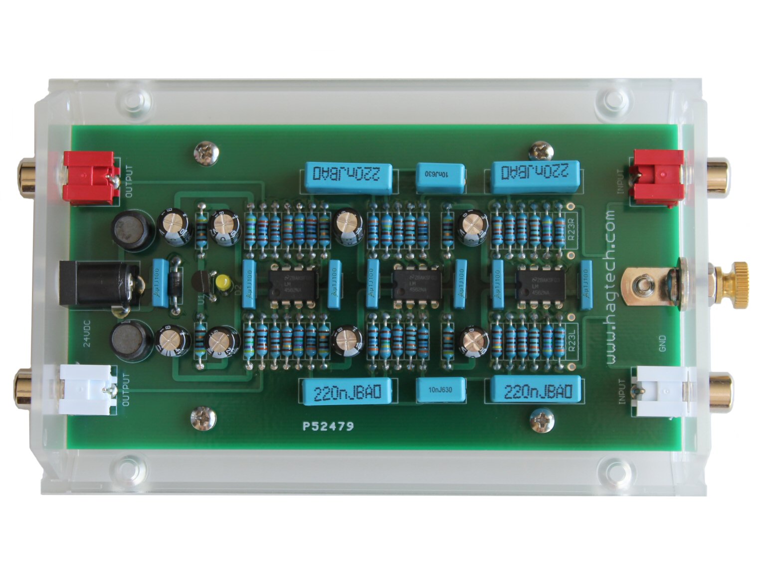
No idea what you mean by installing the parallel pair of RCAs as load plugs. I can set the load with a resistors on the board, right?
Sorry, I thought you intended to put the Bugle PCB in a different (metal) case.
Yes, you can set the load with resistors on the board - but that means it's fixed. Obviously, if you use the stock case, you haven't got any choice - but if you migrate the PCB to a different (earthed metal) case, then you could:
1. remove the PCB-mounted input RCAs and, instead, use wires going to 2x case-mounted RCAs for each channel.
2. use 47K as the default load res on the PCB.
That's what I did with a mate's Bugle, anyway.
Andy
ok, now i get what you mean with the second set of plugs. good idea - even though i think i‘ll stick with my mm carts that need 47k loading for now.
back to my original question. yes i do want to use a metal case. so the question was if the thumb screw (marked gnd on input side) should be isolated from the metal chassis or be connect to it.
back to my original question. yes i do want to use a metal case. so the question was if the thumb screw (marked gnd on input side) should be isolated from the metal chassis or be connect to it.
ok, now i get what you mean with the second set of plugs. good idea - even though i think i‘ll stick with my mm carts that need 47k loading for now.
Some MMs - like Grado wood-bodies - actually sound better at ~35K loading.
Others - eg. classic Japanese MMs - actually sound better at 100K!

Hence, in my own Muse phono stage, I use 100K as the default load and provide load plugs to bring it down to 47K or 35K.
back to my original question. yes i do want to use a metal case. so the question was if the thumb screw (marked gnd on input side) should be isolated from the metal chassis or be connect to it.
With a plastic case, that Ground thumb-screw is connected to signal earth.
If you are going to put the PCB in a metal case (that can be earthed) then:
1. I suggest the best approach is to remove the PCB-mount RCAs and use case-mount RCAs instead (with I/O wires running from the PCB to the case-mounted RCAs). This enables you to then mount both input & output RCAs on the back-panel ... for neatness.
2. I would then mount a separate Ground post on the back panel (scraping off the anodising/powder-coating on the inside, round the hole for the Ground post, and use a star-washer under the nut, to get connection between the Ground post and the case.
Andy
Andy, thanks that sounds like excellent advice. Could you post a picture of your phono stage? I'd be interested to see how this whole setup with loading plugs looks in the flesh.
So the short answer would be: Yes, the ground screw should connect to the metal case, right? At the same time the RCA shield should be isolated from the case.
On the neatness factor: I was intending on mounting the PCB in the metal case so i can use the input side (2x RCA, GND screw) with the board mounted components. No additional cable length - at least that's my idea. The output and power in would have to be routed to the back of the case where I'd mount a pair of panel mount RCAs and the DC plug. On the front I'd only put a toggle switch for on/off.
hope that makes sense.
I'd suggest isolating the chassis from the ground to begin with, as you can always connect it back later if necessary.
True. When in doubt: trial and error
So the short answer would be: Yes, the ground screw should connect to the metal case, right? At the same time the RCA shield should be isolated from the case.
Correct!!
Andy, thanks that sounds like excellent advice. Could you post a picture of your phono stage? I'd be interested to see how this whole setup with loading plugs looks in the flesh.
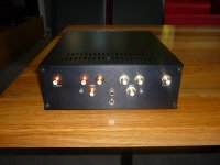
I've attached a pic of the back panel of my 'Muse' - both MC and MM versions. As you can see, there is a triplet of input RCAs plus 1x output RCA, for each channel. Phono cable goes in the bottom (input) RCA ... load plugs ('R' & 'C') go into the others.
In the centre is a Ground terminal (connected to the case) and - as this phono stage is SLA-powered - the charging socket.
On the neatness factor: I was intending on mounting the PCB in the metal case so i can use the input side (2x RCA, GND screw) with the board mounted components. No additional cable length - at least that's my idea.
Not quite! As the Ground terminal is attached to signal ground on the Bugle PCB, if you intend to use the PCB-mounted input RCAs & Ground terminal in your metal case, then you need to drill large holes in the case back, so the input RCAs (and their RCA plugs, if you are going to use metal-barrelled plugs) & Ground terminal don't touch the case.
The output and power in would have to be routed to the back of the case where I'd mount a pair of panel mount RCAs and the DC plug. On the front I'd only put a toggle switch for on/off.
I suggest you will get better sound if you use a linear DC power supply like an Sbooster, rather than the SMPS which is normally supplied with a Bugle. Sboosters have their own power switch - so no need to build one into the front of your metal-cased Bugle. But put an LED on the front panel, to show you when it's on!
Andy
Attachments
Correct!!
Not quite! As the Ground terminal is attached to signal ground on the Bugle PCB, if you intend to use the PCB-mounted input RCAs & Ground terminal in your metal case, then you need to drill large holes in the case back, so the input RCAs (and their RCA plugs, if you are going to use metal-barrelled plugs) & Ground terminal don't touch the case.
Andy
Wait, isn't that a contradiction?
First you say 'correct' to isolating RCA shield from the metal chassis while attaching GND screw to chassis.
In the second quote you suggest to keep RCA shields AND Ground terminal isolated from the chassis.
Sounds like a plan. That's how i'll do it!
Many thanks!
One other question - 6L6, as obviously you have build a bugle 2. The manual lists a table for 'gain and loading' options. Unfortunately in that table I only find gain options. For 40db it says
R23: empty,
R1: 316,
R3, R8: 1k30.
Do those values give me a loading of 47k or are other resistors responsible for loading?
Gain and loading are two different things. (However that table in the manual is confusing...)
R2 is the 47K load resistor.
R23 is a parallel load resistor for the higher gain settings, as at 50db or 60db it's assumed you'll be using MC cartridge. With R23 empty you'll get 47k loading.
R2 is the 47K load resistor.
R23 is a parallel load resistor for the higher gain settings, as at 50db or 60db it's assumed you'll be using MC cartridge. With R23 empty you'll get 47k loading.
Wait, isn't that a contradiction?
First you say 'correct' to isolating RCA shield from the metal chassis while attaching GND screw to chassis.
In the second quote you suggest to keep RCA shields AND Ground terminal isolated from the chassis.
Not a contradiction because you said you would keep the PCB-attached input RCA sockets and the Ground terminal. Therefore, you need to keep both isolated from the case.
If you used wires to connect the input RCAs to the PCB (signal & ground) then you would remove the PCB-mounted Ground terminal (which is connected to signal ground) and use a different Ground terminal which is connected to the case - with no wire back to the PCB ground.
Andy
Yes, now I get what you mean! Thanks for explaining it.
The 220nF caps the manual lists are out of stock at mouser (80-PHE426HB6220JR06).
Would it be better to use caps from the same series but higher voltage rating (80-PHE426KB6220JR06)
Or get wima caps with exact same specs (MKP4F032204B00JSSD)
The higher rated Kemet caps are 2mm wider but i guess there should be enough space on the board.
Or no difference at all?
Would it be better to use caps from the same series but higher voltage rating (80-PHE426KB6220JR06)
Or get wima caps with exact same specs (MKP4F032204B00JSSD)
The higher rated Kemet caps are 2mm wider but i guess there should be enough space on the board.
Or no difference at all?
- Home
- Source & Line
- Analogue Source
- Hagerman Bugle 2