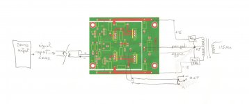
My (limited) understanding is that the AC safety ground is installed by connecting the IEC inlet ground wire bonded securely to chassis right next to the IEC inlet. This is separate from the audio signal ground.
The audio signal ground for unbalanced signal is normally installed from the input of the audio circuit to the conductive chassis. The idea, I thought, is to provide the lowest possible impedance for the input ground, and let any power supply ground or other higher current ground connect from 'farther away' (slightly higher impedance due to longer ground trace or wire).
Am I wrong?
--
My (limited) understanding is that the AC safety ground is installed by connecting the IEC inlet ground wire bonded securely to chassis right next to the IEC inlet. This is separate from the audio signal ground.
--
That is my understanding, too.
")
The audio signal ground for unbalanced signal is normally installed from the input of the audio circuit to the conductive chassis.
--
I refer you back to what you said above (which I've highlighted in red).
As 'dirty' mains earth is connected to the chassis, for safety reasons - I keep audio ground entirely separate from the chassis ... so as not to get mains-earth noise on it.
RCA earth tags are connected to the earth plane on their PCBs.
Andy
I keep audio ground entirely separate from the chassis ... so as not to get mains-earth noise on it.
RCA earth tags are connected to the earth plane on their PCBs.
And the PCBs are earthed where?
The PCB is going to have a trace labeled 'ground' or 'earth'. That has to be connected to some chassis somewhere, or else you're not using your chassis as a shield at all. Perhaps you're floating the audio signal 'ground', letting it get earthed by the power amplifier chassis or similar through the RCA cable connections? (The power amp will certainly have a signal-ground-to-chassis bond at its input. Or at least they usually do.)
http://www.valvewizard.co.uk/Grounding.pdf
Fig. 15.2
"The safety-earth bond should be made to a dedicated screw, close to the mains inlet."
Fig. 15.15b
"The correct place for the ground-to-earth connection is the input of the amplifier."
Last edited:
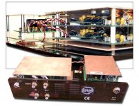
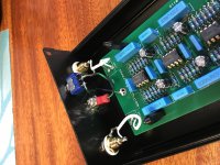
Finished. Put ground stud on case. Attached turntable ground wire. Absolutely perfect. The Hag board is isolated from the case as are all rca’s. Now testing different power supplies!!
PS...the tiny hole in top is to view the led.
PS...the tiny hole in top is to view the led.
Attachments

(The power amp will certainly have a signal-ground-to-chassis bond at its input. Or at least they usually do.)
Mine don't.
Perhaps you're floating the audio signal 'ground'
Yes!
Signal ground is signal ground; chassis ground/safety earth is chassis ground/safety earth - and never the twain shall meet!
or else you're not using your chassis as a shield at all
Que? If the metal case is connected to mains earth ... it's providing a shielded case for the circuitry inside.
Andy
A 40dB RIAA preamp is almost certainly "Pickering" moving magnet 47k loading.
I would say a "40dB phono stage" with a 47K loading is without doubt an MM phono stage. It will cope with most MM carts - not just Pickering.
50dB and 60dB are mostly low-impedance moving coil. These may or may not benefit from a low impedance loading.
"50dB and 60dB gain" are certainly low-impedance moving coil phono stages. They will make a LOMC cart sound its best with a <47K(ie. "low impedance") loading.
The only exception to this is the Grado Statement carts which are 0.5mV output MIs. Which sound their best at about 33K loading.
The custom of using transformers implies a lower impedance though a high step-up, so I guess the carts were mostly designed along low-Z loading.
The "custom of using (step up) transformers (SUTs)" delivers a loading to the cart which is 47K (or whatever the phono stage loading is) divided by the square of the SUT coil ratio. So a 1:10 SUT delivers 470 ohms from a typical MM phono stage. (This can be reduced, if necessary, by putting a resistor across the secondaries of the SUT.)
If the optimal loading for the cart is higher than that which the SUT delivers ... you are actually stuffed!
But part of "47k" is really cable and tube capacitance. When we go lower Z cartridge the capacitance matters much less, the resonance tends to be supersonic, the loading not real critical.
Errhh, no! LOMCs - which prefer vastly <47K loading - are in general insensitive to "cable and tube capacitance". But the resistive loading is critical.
Unlike MMs - which are sensitive to:
* cable capacitance,
* and "tube capacitance" - by which I think you mean Miller capacitance.
Obviously if your cart specs have a number, use that.
The loading spec provided by the mfr is typically the lower end of a potential range. For instance, specs for the Benz LP I used to have say ">470 ohms" (which was 14x the coil impedance).
My experience is that there is an optimum loading between 10x and 100x coil impedance.
Andy
Originally Posted by rongon
Perhaps you're floating the audio signal 'ground'
Yes!
Signal ground is signal ground; chassis ground/safety earth is chassis ground/safety earth - and never the twain shall meet!
Originally Posted by rongon
or else you're not using your chassis as a shield at all
Que? If the metal case is connected to mains earth ... it's providing a shielded case for the circuitry inside.
I'm not seeing how the earth safety ground shields the signal circuitry if the unbalanced signal 0V is left floating in the RIAA preamp.
Perhaps the cable from the turntable/tonearm being grounded to the chassis 'grounds' the signal? Then the unbalanced output 0V from the preamp is 'grounded' at the power amp (or line preamp) input...?
I've always followed the dogma that the signal ground 0V should be connected to chassis at the amplifier input. This is of course completely separate from the earth safety ground, which is connected to chassis at the AC cord entry to the chassis of the power supply (whether or not that is in the same chassis as the audio signal circuitry).
Finished. Put ground stud on case. Attached turntable ground wire. Absolutely perfect. The Hag board is isolated from the case as are all rca’s. Now testing different power supplies!!
PS...the tiny hole in top is to view the led.
Just curious... The Hagtech pcb has a big ground stud near the inputs. Did you leave that disconnected?
I would say a "40dB phono stage" with a 47K loading is without doubt....My experience is that there is an optimum loading between 10x and 100x coil impedance. Andy
Thank you for your additional interpretation.
I'm not seeing how the earth safety ground shields the signal circuitry if the unbalanced signal 0V is left floating in the RIAA preamp.
Because the signal circuitry is inside a metal case which - when 'safety earthed' by connecting the case to the mains earth tag - forms a Faraday shield.
I've always followed the dogma that the signal ground 0V should be connected to chassis at the amplifier input. This is of course completely separate from the earth safety ground, which is connected to chassis at the AC cord entry to the chassis of the power supply
Whereas I have always followed the dogma that signal ground should be isolated from mains earth - ie. the case.
However, if you want to connect signal ground to the case ... I would've thought it is best to do this as a 'star earth' - ie. use the earth bolt which attaches the wire from the IEC earth pin to the chassis.
(whether or not that is in the same chassis as the audio signal circuitry).
If you make a 2-box component - so that the PS is in a separate case to the signal processing - I would suggest:
1. the PS case has an earth safety ground.
2. but an earth wire goes from the PS case to the signal processing case (so the signal processing case is still a Faraday shield.
Andy
I would suggest:
a] connecting the AC mains Safety Ground/Protective Earth to the chassis near where the AC power enters the chassis.
b] connecting the audio circuit common (aka ground) near the input connectors.
* * * * * * * *
Two different tasks, two different connection points.
a] connecting the AC mains Safety Ground/Protective Earth to the chassis near where the AC power enters the chassis.
b] connecting the audio circuit common (aka ground) near the input connectors.
* * * * * * * *
Two different tasks, two different connection points.
Last edited:
I would suggest:
a] connecting the AC mains Safety Ground/Protective Earth to the chassis near where the AC power enters the chassis.
b] connecting the audio circuit common (aka ground) near the input connectors.
* * * * * * * *
Two different tasks, two different connection points.
Agree with a].
But why do you want/need to do b]?
Andy
On achieving shielding within an acrylic case: Tom Evans produced reportedly quiet phono stages (The Groove) using copper plate sandwiches inside a plastic case. He employed separate power supplies but it's unclear how his grounding was wired. The Pearl 2 has a bridge that isolates earth and signal/power grounds but seems to connect the signal chassis to the signal ground... which seems counterintuitive to me.
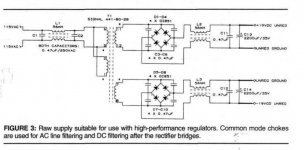
I'm struggling with a slightly different aspect of grounding in phono and line stages. I'm trying to square advice to use separate transformer secondaries, bridges and caps for each pole-channel (4 in all) -- per the Jung-Didden-Galo PSU and regulation -- and keeping signal grounds and power grounds c/w PC ground planes, separate -- as suggested by Richard Marsh.
Marsh recommended connecting the two together at the transformer centre tapped secondary (which J-D-G don't have) So... where to connect these power grounds? I guess both signal and power grounds would be run separately to a star ground at an isolated ground post between the input jacks. I don't know if that actually works. For safety I presume that this could be wired back through the umbilical and connected to a bridge per the Pearl.
Thoughts?
Attachments
Just curious... The Hagtech pcb has a big ground stud near the inputs. Did you leave that disconnected?
Attachments
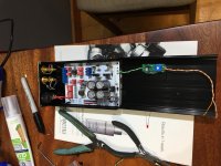
Gonna compare the Hag to The Muff....
Ooo I'm very interested to hear your impressions on this comparison.

- Home
- Source & Line
- Analogue Source
- Hagerman Bugle 2