Does anyone rember this?
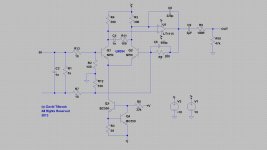
This project was designed by David Tilbrook and presented in ETI Magazine Sept, Oct, Nov 1981. (now I'm feeling my age).
I recently extracted my original MC preamp from the junk box (where it has languished for 26 years) with the idea of refurbishing it.
Have attached a copy of the circuit diagram.
Any suggestions for improvment, I assume better grade of caps and some resistors will make a difference. What about the semi's?
I will probably power it with a shunt reg PSU, and drive it with a Supex SDX1000 (if it can be repaired).
There maybe other good designs I should consider building, the down side to this forum is there is so much wonderful information you can overload reading through it.
Yes, I just found that one again today.
I've been looking at doing a new MM preamp and in amongst my old papers from years ago I found some pages torn out of ETI, a feature article by Mr Tilbrook entitled 'Pickup Amplifier Design' dated Jan 1982. It mostly goes through the design of an MM preamp but it has the very same MC preamp circuit on the last page. I've just noticed the Fig.5 title is also the same so we may be looking at the same article just published a few months apart in NZ and UK. Do you want a scan to compare ?
The end of the article mentions a 2nd installment with a practical design but I don't have that, I don't really need it either. The RIAA accuracy in his MM preamp is not that accurate, deviation from RIAA is about 2.3dB total. It's the same topology as one recently posted by Calvin here: Calvin MM preamp
The MC preamp has no EQ so should be flat anyway.
I'd probably build it if I needed to get an MC up and running, it's simple, should be quick and easy to build, probably quite low cost too. Just got to find an LM394 - you can still get them on Ebay, hopefully not fakes. Modern equivalents seem thin on the ground or expensive like MAT12
Hi,
the Elektor Preamp published in 1986 used this kind of input stage with a triple of paralleled MAT02 transistors which were biased at 1mA. Gain was switchable in four steps to accomodate for MM and MC pickups. As Opamps they used the -at that time quite popular- OP27. A passive 2120Hz-stage and a active 50-500Hz-stage utilizing series feedback followed. The phono stage was part of a full fledged Preamp, later reviewed in a Stereoplay test, where it scored with good measurements but wasn't rewarded with a equally good sonic judgement.
In following years Elektor used this topology again for a standalone balanced input MC-Pre using a single PNP complementar MAT03.
Sergio Franco showed the triple-MAT02-OP27 Topology in his excellent book "Design with Operational Amplifiers and Analog Integrated Circuits" as an example for an ultra-lownoise OPamp.
Values given in the book:
En 0.5nV/sqrHz
Fce 1.5Hz
In 1.5pA/sqrH
Aol 3xexp7
GBP 150MHz @A=1000
CMRR 130dB
DVos/DT 0.1uV/°C
A gain cell with truely excellent values for an OPamp, though modern Devices offer similar at much less cost, PCB space, Effort and hassle.
I think that this effort only makes sense nowadays for a lowoutput or lowestoutput MC input stage, striving to achieve best measurement figures.
jauu
Calvin
ps: using JFETs and cascoded JFETs instead of the bipolar Duals, Kenwoods Basic C1, L07C and L1000C Preamps featured this Phono stage input topology also. And iirc some Yamaha Preamps also relied on this circuit. Seems to have been quite popular in the late 80s early 90s with japanese designs.
Last edited:
ETI 478MC
Sorry, just to clarify my initial text, I built the ETI 478MC MC pre-amp 30 odd years ago and used it for a few years until the MC cartridge (Supex SDX1000) was damaged.
Both the cartridge and the preamp were thrown in the junk box where they have languished for about 26 years.
I'm having the Supex refurbished, and will require a pre to go with it.
I would like to refurbish my old ETI 478MC board and try it again after all these years.
I'm assuming the caps will need replacing, there are clearly much better quality componets available now but what should I use?
There maybe one or two resistors in the circuit which will also benefit from an upgrade also.
I recognise this isn't a particularly high end product, so I am realistic as to what maybe a good level of component to upgrade to.
So any ideas on reasonable cap (and resistor?) types to use, for this circuit (diagram at top of thread). I will probably have to import as New Zealand is too small to find good stuff on the shelf.
I will also probably build a new design or two (because I can) but I am unsure where to start. I need to spend a little more time getting to know the audio offerings out there.
I would like to try the simple Pre-pre that Salas has designed.
Long term I would like to mount the pre-pre as close to the tone arm as possible (will build a linear terminator type)
All ideas welcome. Thanks.
Tilbrook ETI478MC revisited
Hello SuperTuck,
If I was designing this circuit now I would do things a bit differently. Here are some suggestions for upgrades that you may find interesting.
Firstly it is possible to remove the input capacitor entirely by going to a balanced input topology, as shown in the circuit diagram. Normally the input coupling capacitor is needed, when using bipolar junction transistors, to prevent the input transistors' DC bias current from flowing through the cartridge. Provided that the input differential pair is very well matched (and it will be with the LM394) the balanced topology shown ensures that DC current in the cartridge is reduced to acceptable low levels. The downside is a small increase in noise, due to the thermal noise of resistors R7 and R13, which can be decreased if you need more gain. With the values shown gain is 26dB, well below that provided by the original circuit, but suitable for most medium output MC cartridges. Reducing R7 and R13, to 5R for example, will decrease the contribution to the noise from these resistors by 3dB. In any case, the noise performance should still be very good.
I think the op-amp should be upgraded to a modern pin-compatible device. There are many potential candidates, but the LT1115 form Linear technology is a good place to start. Changing op-amps has the potential to make these types of circuits unstable, depending on the high-frequency phase characteristics of the device, but with the LT1115 the only change that I think is necessary is to add a 100R resistors in series with the 1n capacitor C5. I am 99% certain that the circuit will the totally stable, but I do not entirely trust the SPICE models I have for the LM394. So if anyone can post a SPICE model for the LM394 they are confident is accurate, I can double check this. Capacitor C7 was required because the NE5534 is not unity gain stable, and should be removed if you are using the LT1115.
Assuming that the output load is 47k, the output capacitor can be reduced to 2uF, in which case a high quality audio grade capacitor can be used such as a metalised polypropylene or better. R10 is shown as 47k on the circuit, but simply provides a ground reference for the output side of C9. It can be increased as necessary, depending on the input coupling of the following stage. Alternatively, both R10 and C9 can be removed totally if the following stage is ac coupled and permanently connected.
With the values shown the input impedance is approximately 1k//200R, as determined by R1, R2 and R12. I have found that 200R is a good loading impedance for a large number of MC cartridges, despite the recommendation of some cartridge manufacturers for lower load impedances, in which case R1 can be removed. Capacitor C2 is for cartridge loading, and can be changed to suit your particular cartridge.
There are various other resistor changes as shown on the circuit, but it is sufficiently close that it can be built using the same PC board.
You mentioned that you will probably be making shunt regulators for the preamp, and I agree that is a good idea. I would increase the supply voltage to the +/- 18 V shown on the diagram (but not higher if you decide to go with the LT1115).
With these changes this should be a very good MC preamp. The frequency response at low frequencies will be 3dB down at less than 2 Hz and extend to over 1MHz. THD and IM should be unmeasurable for a gain of 26dB, and will remain extremely low even at significantly higher gains, and noise performance will be comparable to the original circuit. Although I have not built this particular circuit, I have had many hundreds of hours of listening tests with a very similar, although fully discrete circuit, with a similar topology, which sounds very good.
In any case it would be an interesting experiment to do. If you decide to try it, please let me know how you go.
regards
David Tilbrook
Attachments
Hi David
Thanks so much for taking the time to re-visit this project. The balanced input is brilliant, as I'm building a Terminator style arm and the tone arm wires hang in the air to allow the arm to slide. It always concerned me that the potential to pick up noise would be an issue, particulary as I have quite abit of PC related gear in the near vicinity. The LM394's are no longer supplied by National, but Texas still make them $24ea at Farnell (ouch) there are plenty that are cheap on EBay but are prob chinese knock-offs. I will start cobbling this together over the winter as I'm still working on the turntable (had to make a furnace, a tool post grinder and a spindle sander just to start the turntable, all on a budget of ziltch).
I wont know if I have enough gain until the MC has been repaired and set up.
I have not had a TT for many years and the MM input on my Plinius has never seen any action. So I am starting from scratch.
Thanks again for the time you put into my inquiry.
I made many of your projects in ETI in my younger days, and learnt much from your well written articles. The demise of ETI and EA has been sad for the industry as many young enthusiasts learnt their electronics skills this way
Hi,
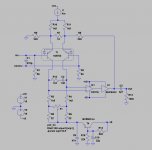
I´m not quite sure if the feedback configuration in #6, in that inverting input and feedback meet at the input/Pickup, is really working as intended.
It must be taken special care with the delicate coils of MCs that no, or at least safely small, currents are injected into the pickup.
I didn´t check the circuit on that, but will the cartridge be safe any time even at switch-on/off, or could the Opamp drive lethal currents into the pickup?
Attached is a slightly different configuration (here shown with the bipolar PNP MAT03, which has a slightly lower noise voltage figure than its NPN counterpart MAT02 but basically the same structure), which breaks up the feedback and input part, by connecting the feedback to the input transistors´ emitters. Now only the input bias current mismatch of the transistors Gates may ´stress´ the pickup coils.
With the bias current already in the low µA-range and a specced current mismatch of 3% any cartridge should be safe.
Also a Buffer is added behind the OPamp. The Opamp alone is not specced for such such low load impedance as R8 here and in #6.
It´ll probabely suffice without the buffer due to the small signal voltages and current demands, but current requirements of the feedback loop and the Opamps current capabilities should be considered.
jauu
Calvin
Attachments
Last edited:

Correction to my post re input impedance.
Re-reading the thread I see I made a typo in my original post. The input impedance, of course, is 20 ohms not 200 as I incorrectly stated. The gain is around 28dB with zero cartridge impedance, dropping to around 26dB with a cartridge source impedance of around 5 ohms.
If higher input impedance is required, it is also possible to introduce an asymmetric pseudo-balanced input topology, which still results in minimum bias current flowing in the cartridge. My notes on this are still buried in boxes after moving house, but I can dig them out if needed.
Having trouble scourcing the LM394 matched pairs for the ETI 478MC. Does anyone know any availability or alternative device please ?Hello SuperTuck,
If I was designing this circuit now I would do things a bit differently. Here are some suggestions for upgrades that you may find interesting.
Firstly it is possible to remove the input capacitor entirely by going to a balanced input topology, as shown in the circuit diagram. Normally the input coupling capacitor is needed, when using bipolar junction transistors, to prevent the input transistors' DC bias current from flowing through the cartridge. Provided that the input differential pair is very well matched (and it will be with the LM394) the balanced topology shown ensures that DC current in the cartridge is reduced to acceptable low levels. The downside is a small increase in noise, due to the thermal noise of resistors R7 and R13, which can be decreased if you need more gain. With the values shown gain is 26dB, well below that provided by the original circuit, but suitable for most medium output MC cartridges. Reducing R7 and R13, to 5R for example, will decrease the contribution to the noise from these resistors by 3dB. In any case, the noise performance should still be very good.
I think the op-amp should be upgraded to a modern pin-compatible device. There are many potential candidates, but the LT1115 form Linear technology is a good place to start. Changing op-amps has the potential to make these types of circuits unstable, depending on the high-frequency phase characteristics of the device, but with the LT1115 the only change that I think is necessary is to add a 100R resistors in series with the 1n capacitor C5. I am 99% certain that the circuit will the totally stable, but I do not entirely trust the SPICE models I have for the LM394. So if anyone can post a SPICE model for the LM394 they are confident is accurate, I can double check this. Capacitor C7 was required because the NE5534 is not unity gain stable, and should be removed if you are using the LT1115.
Assuming that the output load is 47k, the output capacitor can be reduced to 2uF, in which case a high quality audio grade capacitor can be used such as a metalised polypropylene or better. R10 is shown as 47k on the circuit, but simply provides a ground reference for the output side of C9. It can be increased as necessary, depending on the input coupling of the following stage. Alternatively, both R10 and C9 can be removed totally if the following stage is ac coupled and permanently connected.
With the values shown the input impedance is approximately 1k//200R, as determined by R1, R2 and R12. I have found that 200R is a good loading impedance for a large number of MC cartridges, despite the recommendation of some cartridge manufacturers for lower load impedances, in which case R1 can be removed. Capacitor C2 is for cartridge loading, and can be changed to suit your particular cartridge.
There are various other resistor changes as shown on the circuit, but it is sufficiently close that it can be built using the same PC board.
You mentioned that you will probably be making shunt regulators for the preamp, and I agree that is a good idea. I would increase the supply voltage to the +/- 18 V shown on the diagram (but not higher if you decide to go with the LT1115).
With these changes this should be a very good MC preamp. The frequency response at low frequencies will be 3dB down at less than 2 Hz and extend to over 1MHz. THD and IM should be unmeasurable for a gain of 26dB, and will remain extremely low even at significantly higher gains, and noise performance will be comparable to the original circuit. Although I have not built this particular circuit, I have had many hundreds of hours of listening tests with a very similar, although fully discrete circuit, with a similar topology, which sounds very good.
In any case it would be an interesting experiment to do. If you decide to try it, please let me know how you go.
regards
David Tilbrook
Having trouble scourcing the LM394 matched pairs for the ETI 478MC. Does anyone know any availability or alternative device please ?
Use MAT02 or MAT12 from Analog Devices.

Hi,
or look for the very similar but alot cheaper THAT 300Series.
jauu
Calvin
Not correct. Different package and MUCH lower gain (HFe)
If you want cheaper use SSM2210.
Have just resurrected this pre I put together in 1982 as a result of my kids getting me back into vinyl again. (now trendy) I have a Project Perspective TT with a Ortofon MC30 Supreme cartridge.
It still sounds remarkably good and sounds much better with vinyl on both MM and MC cartridges than the Cambridge 650P I bought to go with my daughter's first TT (Project Debut Carbon).
I made up an external box for a large Toroid for the AC supply rather than the tap off the old power amp tranny. The Volume pot was upgraded (Cermet?) and I use the Line outs (not Monitor outs) straight to monoblock amps.
Now I'm not so sure I should'nt have just modded /upgraded this pre rather than buying Metaxas, Naim and Ming Da preamps over the years.
Last edited:
- Status
- This old topic is closed. If you want to reopen this topic, contact a moderator using the "Report Post" button.
- Home
- Source & Line
- Analogue Source
- MC PRE-AMP ETI 5000