Hello can anyone help with schematics or diagrams of any Pink Triangle turntable PSU's
I bought an Export as a project and then bought an Export PSU board and LPT PSU board to try and get it running.
With the Export PSU I can't get the speed to set properly. So For the moment I am using the LPT PSU wired up and running externally.
The only problem here being the top plate switch on the LPT is not in circuit.
I would like to either try and repair the Export PSU board and or work out what I need to do to use the switch in conjunction with the LPT board or the Export board.
I have tried replacing caps on the Export board and tried it with two different motors, with the correct motor fitted to the turntable the export board will either run the motor very slowly or just vibrate the motor like a 3 phase motor that is single phasing, I have tried another spare Linn motor and that runs fine but slowly.
Any diagrams, help or ideas would be most welcome
thanks
Allen
Hello and thanks for replying.
Sorry I can't seem to attach pictures, I have given it a few goes and keep rescaling the pictures down so that they are now way within the upload limits but they still won't upload, if you PM me with your email address I will send them over.
I am down on the Kent coast in Whitstable so quite a way from you
 I've started a new thread in forum problems for the image attachment issue. http://www.diyaudio.com/forums/forum-problems/228752-problem-uploading-attachments.html posts moved to there.
Pink Triangle PSU help
Ok
I have copied them upto my websoace and then copied them from there, I have no idea why i can't just upload them but either way they are up.
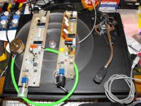
The PSU I am using is the used looking one with the heat marks and replaced resistors nearest the tonearm, this one is the same as I have in my LPT.
The other is the one that I think is an export PSU, this looked unused and I suspect was either a reject or failed early on in it's life.
Thanks
Allen
Ok
I have copied them upto my websoace and then copied them from there, I have no idea why i can't just upload them but either way they are up.
The PSU I am using is the used looking one with the heat marks and replaced resistors nearest the tonearm, this one is the same as I have in my LPT.
The other is the one that I think is an export PSU, this looked unused and I suspect was either a reject or failed early on in it's life.
Thanks
Allen
Attachments
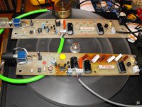
Allen, they are both the same circuit, just a few layout changes/updates between them. It's a relatively simple PSU with variable speed control based on the frequency of one of the small canned crystals next to the speed dial. As long as the IC's are still available it should be easy enough to fix assuming the motor isn't goosed.
If it looks like one phase is bad then replace the larger dipped orange cap, it'll be a 0.22uf polyprop or similar.
Can you fire it up and read the AC voltages coming off the small white connector block as follows?
Red-blk
Green-blk
Red-green.
If it looks like one phase is bad then replace the larger dipped orange cap, it'll be a 0.22uf polyprop or similar.
Can you fire it up and read the AC voltages coming off the small white connector block as follows?
Red-blk
Green-blk
Red-green.
OK thanks
I guessed they were basically the same with the exception of the export having the socket on the back that I assumed the plug from the switch on the turntable would use to pick up the motor power and also switch it off
The voltages when trying to run the motor are not stable I am assuming because it is shifting frequency and are roughly:
red to black is between 40 and 52 Vac
green to black is between 25 to 40 Vac
red to green is between 58 to 65 Vac
with the psu in idle then it is more stable and gives
red to black is 44 Vac
green to black is 28 Vac
red to green is 38 Vac
from memory I did play about with the poly caps and the value in there is probably wrong, it is a 0.68uf at present and that's what the LPT board has in it but I can't remember if I copied that or the 0.68uf was in there to start with.
I never got it to run the motor fitted in the turntable but could get it to run the motor wired to it now if I gave it a helping hand. I get the same result on either speed which got me looking at those caps in the first place.
As I say it's all a long time ago and I couldn't find a schematic for it and moved on to something else bad have now dug it out to play with again.
Thanks
Allen
Ok I have had another look at the two boards
The electrolytic on the other side of the motor in the LPT is a 33uf but the one in the export was a 100uf.
All I had to hand was a 22uf of a high enough voltage so I put that in.
It now runs the motor but the speed is still slightly out, close but not quite there.
I have ordered some 33uf Caps but am guessing that it's the difference between the two caps either side of the motor that gives the shift, so if I drop the 0.68uf poly to something like a 0.47uf would that give a similar result?
Also am I right in thinking that when the motor is wired to the switch board on the top plate of the turntable and the flying lead with the din plug from the switch board is plugged into the export PSU board after the jumpers that are in the din socket now are taken out that the switch should stop and start the turntable?
Thanks
Allen
The AC voltages with the motor running should be rock solid, maybe a few mV of drift but nothing more than that. Unplug the motor from the connector block and take the voltages again please.
What's the motor manufacturer and part number, i'll look up the specs for you and calculate a nominal value.
What's the motor manufacturer and part number, i'll look up the specs for you and calculate a nominal value.
Looking through the change logs for these decks it looks like there was a number of different motors used, some with series coils which require 0.68uf and some which run on the standard 0.22uf.
Might be worth trying 0.22uf in there.
Scroll through Will-B's posts on this thread he knows his stuff.
Turntable Forum • Pink Triangle LPT psu
Might be worth trying 0.22uf in there.
Scroll through Will-B's posts on this thread he knows his stuff.
Turntable Forum • Pink Triangle LPT psu
- Status
- This old topic is closed. If you want to reopen this topic, contact a moderator using the "Report Post" button.
- Home
- Source & Line
- Analogue Source
- Pink Traingle PSU help