improved bass response by moving coupling cap
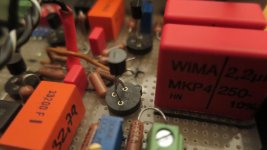
Update: my soldering iron did not run cold after my last postings. In my newest, cleanest version i applied some helpful changes. I use 50 ohm trimmers as source resistors only for the second transistor stage. Cant hear the difference to fixed resistors, but it helps me searching for the sweet spot biasing point. Together with the variable VCC it gives me more different ways to set the voltages and biasing points on the first jfet (with fixed Rs of 12R7) and on the second jfet.
But the biggest improvement came from moving the coupling cap at the output of the first jfet stage to the input of the second stage. I saw a lot of people in the forums doing this with the pacific topology. But i did not understand why it would sound different.
Now i thought about it again and realised that right after the first jfet stage the frequency spectrum is still bended according to the RIAA curve.
But after the RIAA filter stage, right in front of the second jfet stage, the signal is low level, but already "flat". If you place a coupling cap there it will see a higher amount of bass (compared to the amount of highs) in the signal. In combination with the gate-to-ground resistor of the second jfet (220k in my case) a mild highpass with fc around 3 Hz is formed without too much attentuation of the audible band.
I guess there are more professional ways to describe this, sorry
Will come back with my actual schematic for everyone that might find this thread somewhen in the future
Last edited:
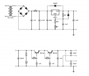
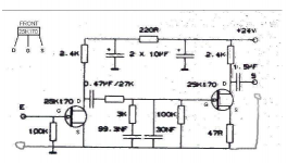
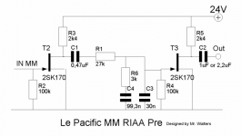
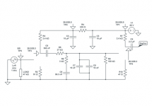
That was about my hand drawing. But I wanted it cleaner for archive file.Comprehensive schematic.
So I've done my homework, nice little supply with top circuit in a remote case, bottom one in the phono's one.
The software is iCircuit on Mac OS, lacking parts but I guess they're working on it.
Attachments
Looks good, nice drawing How does your power supply sound like? Mine is exactly the same lm317 circuit followed by the capacitance multiplier, but powered by a smps wallwart. I checked different models of wallwarts, some are noisy, but mine (the cheapest Voltcraft model) seems to be dead quiet..
I found some hints in the web, that it is good when all the capacitors of the capacitance multiplier share one star ground point. Changing the capacitor ground rail to a star ground totally killed the last amount of hum in my case..
Example: http://sound.whsites.net/p15_fig3.gif
How does your power supply sound like? Mine is exactly the same lm317 circuit followed by the capacitance multiplier, but powered by a smps wallwart. I checked different models of wallwarts, some are noisy, but mine (the cheapest Voltcraft model) seems to be dead quiet.. I found some hints in the web, that it is good when all the capacitors of the capacitance multiplier share one star ground point. Changing the capacitor ground rail to a star ground totally killed the last amount of hum in my case..
Example: http://sound.whsites.net/p15_fig3.gif
Last edited:
Hi, sadly the shape of my circuit is the only one that fits in my tiny phono box, it's only a quick build with mostly drawer spare parts (but the JFet). Anyway it's a very good sounding "waiting until better" phono pre, and quite silent!
Let's enjoy the LPs And thanks that guy named Salas!
Let's enjoy the LPs
And thanks that guy named Salas!finally my Hagtech inverse Riaa unit arrived I did some basic square wave measurements on some the phono preamps using the inverse Riaa.
Phono Input Allen Heath xone 92: weak bass response under 50 Hz, bass boost at about 70 Hz, not-so-square looking waves at the output.
No-Name opamp phono preamp: way better looking square wave response.
Pacific: very good looking square wave output at 100Hz, 1khz and 10khz. At 10khz the square wave output looks like there is too much attentuation at high frequencies. But keep in mind that the Hagtech inverse Riaa comes with an additional zero at 50khz, which is not represented in the circuit i used. So the square wave output will always look a bit "rounded" as long as i do not implement the "missing Neuman constant" at 3,18us.
After my holidays i will continue with more comprehensive measurements including some integrated phono preamps. Very interesting topic!
I did some basic square wave measurements on some the phono preamps using the inverse Riaa.Phono Input Allen Heath xone 92: weak bass response under 50 Hz, bass boost at about 70 Hz, not-so-square looking waves at the output.
No-Name opamp phono preamp: way better looking square wave response.
Pacific: very good looking square wave output at 100Hz, 1khz and 10khz. At 10khz the square wave output looks like there is too much attentuation at high frequencies. But keep in mind that the Hagtech inverse Riaa comes with an additional zero at 50khz, which is not represented in the circuit i used. So the square wave output will always look a bit "rounded" as long as i do not implement the "missing Neuman constant" at 3,18us.
After my holidays i will continue with more comprehensive measurements including some integrated phono preamps. Very interesting topic!
finally my Hagtech inverse Riaa unit arrived
Yes, a very useful device!
But keep in mind that the Hagtech inverse Riaa comes with an additional zero at 50khz, which is not represented in the circuit i used.
I did not know that. Is it mentioned in the Hagtech documentation ... and I missed it?
Andy
Unlike traditional networks, the iRIAA Filter includes a correctly placed upper 3.18us (50kHz) corner in its transfer function.
Quote taken from the sales page of hagtech IRiaa2
It should have been a switchable feature IMHO
I agree! That would make measuring accurate when it comes to old designs that did not use this fourth corner at 3.18us.
Maybe i will build myself a passive RIAA with the "classical curve" / without the corner at 3.18us.
some updates and pictures
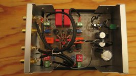
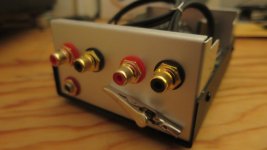
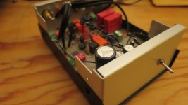
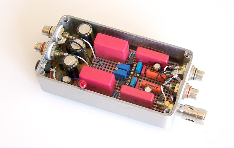
Hey all, still got that jFet fever.. I just wanted to share some pics of one of my last builds. It is build using perfboard and silver wire. I used sockets for the jFets to be able to switch them quick.
There are 4 resistors on the input that can be switched using the dip switches. They are to adjust the input impedance of the preamp in 16 steps from 17kohm to 150 kohm. I stole this idea from muffsy preamp documentation and i am very happy with it. If i would like opamps i would try his cnc clones for sure..
I used HiFi2000 economy case and I think its great for experimental use. Of course it doesnt feel like an expensive, classy case, but it turns your prototype pcb into a usable device for only 6 Euros.
In another build I experimented with an additional 98R resistor in front of the smaller cap in the Riaa filter section (32,8 nF). That should implement the "missing time constant" or technically speaken add a zero at 3.18 µS. Can't hear a difference with my ears, but measures a little better when using the Hagtech inverse Riaa (which implements the fourth time constant into its filter network).
That build measures a total gain of about 42 dB (i am still to stupid to do the gain maths right). That is a very suitable gain structure for my Denon DL-110.
It also plays fine with MM Carts up to 5mV@1kHz nominal output.
Next step will be to try a salas folded phono ;-) But first i have to stop soldering and start moving to my next flat.
Thanks again to everyone who helped me out and answered a lot of questions
Attachments
Nice work! Enjoy your LPs now =)
Or was it the other way around?!
Me too! That guy is so annoying with his great projects, I hate him! My (empty) bank (account) saved me from ordering one from the running GB. I love it.Next step will be to try a salas folded phono ;-)
Or was it the other way around?!

Now THAT's Just Too Cool 4 School !
.
Hi Malefoda
I have been following your story Thread on & off here for a few years.
I have loved the look of 'Le Pacific' & all it's variants for a while now.
I must have a go one day !
I gotta say ... WOW ! that is some super-slick building you have ended up with.
I thought you might have swapped the DIY soldering-iron for a store bought preamp at one point.
It has taken a few years !!
But that lil' box of tricks of yours is a masterpiece & a Faberge egg of the RIAA type !
CONGRATS !
Si.
I hope the Judges are in a good mood today.

.
.
Hi Malefoda
I have been following your story Thread on & off here for a few years.
I have loved the look of 'Le Pacific' & all it's variants for a while now.
I must have a go one day !
I gotta say ... WOW ! that is some super-slick building you have ended up with.
I thought you might have swapped the DIY soldering-iron for a store bought preamp at one point.
It has taken a few years !!
But that lil' box of tricks of yours is a masterpiece & a Faberge egg of the RIAA type !
CONGRATS !
Si.
I hope the Judges are in a good mood today.
.
Hi,
thanks for good words, but don't know if sweating, loose appetite and sleep when two resistors are not perfectly parallel or colour rings oriented the same is a gift, sounds more like a disease to me. =) If only I can build speaker the same way...
BTW, once again I must payback 50% of the thanks to that guy from "La" Callas' country. Crooks!
Booyah!
Follow ... The EAR ! ?
.
" ... sweating, loose appetite and sleep ... "
Hi Malefoda
I'm sorry to hear about the distressing symptoms of intrepid solder slingin'.
I have had similar symptoms to yours over the years.
Perhaps 'Le Pacific' should have a HEALTH WARNING on le schematic !
If your last configuration was how it was finally made ...
... it is interesting to see that you deviated very little from the original Mr Walters version.
It looks pretty much like the only thing you changed/added were 2 source resistors & 2 gate-stoppers.
No tweaking of the EQ parts.
No moving of the coupling capacitor to after the EQ.
No extra 1M resistor on the output.
?
I have noticed in following various peoples 'Le Pacific' builds over the years ...
... that if the cartridge is loaded OK, there is no oscillation & the JFETS are operating OK ...
... the subjective reaction to the 'original' design is almost always very good !
It has always seemed to my understanding that the EQ whilst not technically 'ruler flat' ...
... actually deviates very little from 'ruler flat' & sounds subjectively good to listen to.
All sorts of room, speaker & cartridge colouration are probably always way more 'out' !
I was just interested to observe that your build is very 'original' ...
... perhaps only a few electrons difference to 'La Maison Du Audiophile' sound ...
... before the flood of cheap & easy to use computerized test & measuring hardware/software.
An era when 'the ear' was BOSS ! ?
?
Si.
.
.
" ... sweating, loose appetite and sleep ... "
Hi Malefoda
I'm sorry to hear about the distressing symptoms of intrepid solder slingin'.
I have had similar symptoms to yours over the years.
Perhaps 'Le Pacific' should have a HEALTH WARNING on le schematic !
If your last configuration was how it was finally made ...
... it is interesting to see that you deviated very little from the original Mr Walters version.
It looks pretty much like the only thing you changed/added were 2 source resistors & 2 gate-stoppers.
No tweaking of the EQ parts.
No moving of the coupling capacitor to after the EQ.
No extra 1M resistor on the output.
?I have noticed in following various peoples 'Le Pacific' builds over the years ...
... that if the cartridge is loaded OK, there is no oscillation & the JFETS are operating OK ...
... the subjective reaction to the 'original' design is almost always very good !
It has always seemed to my understanding that the EQ whilst not technically 'ruler flat' ...
... actually deviates very little from 'ruler flat' & sounds subjectively good to listen to.
All sorts of room, speaker & cartridge colouration are probably always way more 'out' !
I was just interested to observe that your build is very 'original' ...
... perhaps only a few electrons difference to 'La Maison Du Audiophile' sound ...
... before the flood of cheap & easy to use computerized test & measuring hardware/software.
An era when 'the ear' was BOSS !
?Si.
.
Attachments
It sounded not that great
.
Hi Malefoda
OK ... But with fake Toshs in the trash ...
... Hot new PSU ...
... & of course top build quality ...
... it sounds good now right ?
What did you do to your EQ that is different to your final schematic then ?
Top hi-end parts ?
Just curious.
You DO like the final result ... right ?
Si.
.
.
Hi Malefoda
OK ... But with fake
Toshs in the trash ... ... Hot
new PSU ... ... & of course top build
quality ... ... it sounds good now right ?
What did you do to your EQ that is different to your final schematic then ?
Top
hi-end parts ? Just curious.
You DO like the final result ... right ?
Si.
.
C3 (on the post#47) higher value, and no, no high-end parts, matched Toshiba and parts, other parts I do have in drawers. BTW Wima MKP10 are said not that bad, few MKT caps also, I guess hand matching helps. Steve Clark's riffs sound great at that what's matter for that year to build little monster in a shiny egg! That's just a waiting cheap phono pre for me, but I can live with it in fact
Last edited:
- Status
- This old topic is closed. If you want to reopen this topic, contact a moderator using the "Report Post" button.
- Home
- Source & Line
- Analogue Source
- Pacific RIAA phono pre: failure!