Hi there!
happy new year to all")
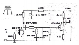
here I go with my freshly soldered RIAA Pacific, this very one but 47k input load.
The PSU is a linear one nicely smoothed, then a clean lm317 based supply, 21V (tx limts vs voltage drops
The thing plays records, RIAAses it, preamplifies it.
But it's unlistenable! On "S" and on some highs it's saturated, eachtime, each records, Shure M91ED, AT95E, Toshiba TD, Denon TD...
And these were playing fine with an integrated with a simple opamp design.
Something strange... now clue where too look at, need your help gents!
happy new year to all
here I go with my freshly soldered RIAA Pacific, this very one but 47k input load.
The PSU is a linear one nicely smoothed, then a clean lm317 based supply, 21V (tx limts vs voltage drops
The thing plays records, RIAAses it, preamplifies it.
But it's unlistenable! On "S" and on some highs it's saturated, eachtime, each records, Shure M91ED, AT95E, Toshiba TD, Denon TD...
And these were playing fine with an integrated with a simple opamp design.
Something strange... now clue where too look at, need your help gents!
Attachments
Hi there!
happy new year to all
here I go with my freshly soldered RIAA Pacific, this very one but 47k input load.
The PSU is a linear one nicely smoothed, then a clean lm317 based supply, 21V (tx limts vs voltage drops
The thing plays records, RIAAses it, preamplifies it.
But it's unlistenable! On "S" and on some highs it's saturated, eachtime, each records, Shure M91ED, AT95E, Toshiba TD, Denon TD...
And these were playing fine with an integrated with a simple opamp design.
Something strange... now clue where too look at, need your help gents!
Could be the RIAA capacitors.
RIAA calculator
http://www.kabusa.com/riaa.htm
Important to use 1% tolerance capacitors & resistors for RIAA.
http://www.kabusa.com/riaa.htm
Important to use 1% tolerance capacitors & resistors for RIAA.
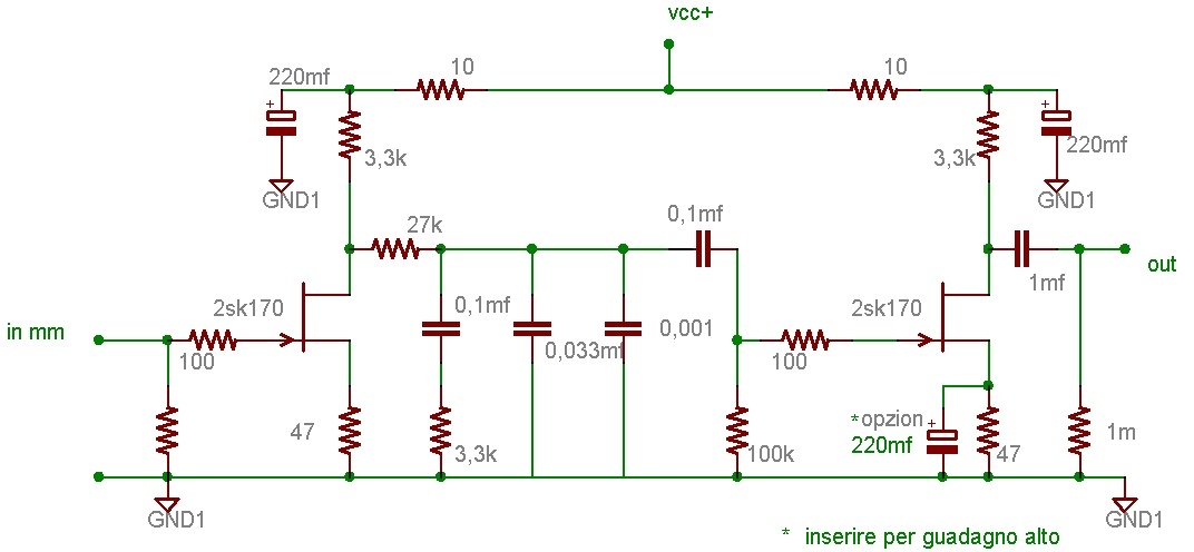
scafas' circuit looks better. it already has the modifications that Kevin [kevinkr] proposes plus a few other useful changes. don't change your RIAA capacitor values at this point. they are so similar to the values in scafas' circuit that you can worry about that later. same for the output cap: not much difference between 1.0 and 1.5uF.
i build a similar phono pre and it sound very good!
Quite close indeed! Hope mine can sing good soon...
Could be the RIAA capacitors.
...
http://www.kabusa.com/riaa.htm
Important to use 1% tolerance capacitors & resistors for RIAA.
I've matched caps to tightest specs and by pairs, maybe not 1% for the 6n8 under the 22n, my dmm is not that good.
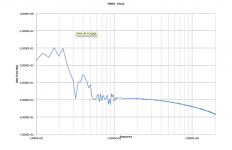
Today with a fellow at work, apprentice engineer, we've had a quick look at the pre freq response. I only can show you that pic of 1k up to 20kHz, but later tests has shown no peak or such in audio band. The RIAA seems innocent.
Try 100 ohm gate stopper resistors on each of the fets and add 47 ohm resistor in series with the source of the first fet for bias.
scafas' circuit looks better. it already has the modifications that Kevin [kevinkr] proposes plus a few other useful changes. don't change your RIAA capacitor values at this point. they are so similar to the values in scafas' circuit that you can worry about that later. same for the output cap: not much difference between 1.0 and 1.5uF.
I've tried with my headamp, in case the 10K attenuator in my amp may trouble the phono, but the same terrible sound. So now I can only attempt theses mods, 2x 100Ω and that 47Ω and for the output caps I have 2.2µF film caps, no problem here as far as I understand.
Let's warm the iron...
Attachments
Oscillation... Good practice to isolate gate from external stray inductance and capacitance, more critical with mosfets than fets, but I have had situations with fairly high transconductance fets that oscillated without gate stoppers. May or may not fix the issue at hand..

Oscillation... Good practice to isolate gate from external stray inductance and capacitance, more critical with mosfets than fets, but I have had situations with fairly high transconductance fets that oscillated without gate stoppers. May or may not fix the issue at hand..
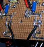
It did fix the issue!
Many thanks, a big hug to ya all
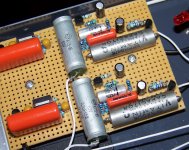
Here is the 100Ω and the tiny 51Ω (it's far smaller than it looks, flash and zoom worsen its appearance, but minimelf and micromelf are a soldering challenge!), and now all flows smooth and dynamic!
Attachments
In fact I'm not sure it means " great " but if it's the case: sadly not :'(
Overall volume is louder on left channel. I've cleaned the mess, solder flux, tracks, close matched the 30n with 2x15, it's almost perfect to the eye. But no use...
Before I go any further I need to say that I find weird that with only the right IC connected to the turntable I get no sound on left (!) and a very slight level of music on right, then left only connected, no sound on right but a terrific loud bassy mess on left... wtf!
May that be some loop at work here? My IC are all connected both wires both sides.
So the question is, if there is nothing odd there, how can I fine adjust gain? That's lying on no solid tests but it sounds like a +2/3dB on left most felt at kHz... (I've said it's "à vue de nez" (translate by "seen-by-the-nose") but that's the best I can tell about what I hear, not TT related as inverting left/right does nothing for this).
I'm glad I did not started a bigger project! That's so annoying...
But I still have to go, time to shift to side B
Last edited:
Check the tone arm wiring, and does the problem swap to the other channel when you swap the left and right inputs?
Left and right inputs both return to ground somewhere on your nicely built boards? (No opens)
Measure dc voltages on fet drains and make sure channel to channel that they match to say within 5 - 10%, if they do not, try to match some fets as variations in transconductance, pinch off voltage, etc. may effect the channel to channel gain match. I would not expect the differences to be that large unless the fets were grossly different.
Even better would be to measure the signal levels directly in each stage, verifying that levels match after the first stage, after the passive eq, and finally the second stage.
Post a reasonably sized picture of each side of the PCB and let us have a look, perhaps something different between the two channels will stand out.
Finally have someone else take a look at your handiwork.
- Status
- This old topic is closed. If you want to reopen this topic, contact a moderator using the "Report Post" button.
- Home
- Source & Line
- Analogue Source
- Pacific RIAA phono pre: failure!