Little Monster In A Shiny Egg !
.
Hi again Malefoda")
I did actually read through your entire Thread the other day ... PHEW !!!
Quite a Marathon & 'only' 16 Pages !
That's ^^ interesting.
So once you had matched genuine Toshs. & other matched parts + bigger C3 & better PSU ...
... in some respects one could say, the only thing different from the original 'Le Pacific' schematic ...
... was really adding in the two 47R & 51R drain resistors.
No gate resistors used either.
Just out of interest, do you recall (more or less) what current JFETs you used ?
I guess BL-grade around 8mA maybe ?
No worries if you don't recall, just curious !
When I made my 1st phono preamp in my late teens ...
... after designing & etching the PCB, which was all new to me ...
... I got all the parts in neat & tidy ...
... only had a Volt/Ohmeter, so couldn't check the RIAA filter parts ...
... the circuit was forgiving in that respect though, with it's series/parallel EQ parts ...
... as above ^^ for the PSU board & the 'Grand Opening Day' was here at last !
Switched on ... & ... IT WORKED !
Dunno about "cheap" ... But it beat the $4!7 out of the shop bought trash I was listening to before that !
I was a Space Egg over the Moon !
I still have it as well.
Stripped down for mods. over some years now.
But one day it will LIVE AGAIN ONCE MORE !!!
I bet your "little monster in a shiny egg" plays Steve Clarks riffs just PERFECT !
t.S.E.c
.
.
Hi again Malefoda
I did actually read through your entire Thread the other day ... PHEW !!!
Quite a Marathon & 'only' 16 Pages !
That's ^^ interesting.
So once you had matched genuine Toshs. & other matched parts + bigger C3 & better PSU ...
... in some respects one could say, the only thing different from the original 'Le Pacific' schematic ...
... was really adding in the two 47R & 51R drain resistors.
No gate resistors used either.
Just out of interest, do you recall (more or less) what current JFETs you used ?
I guess BL-grade around 8mA maybe ?
No worries if you don't recall, just curious !
When I made my 1st phono preamp in my late teens ...
... after designing & etching the PCB, which was all new to me ...
... I got all the parts in neat & tidy ...
... only had a Volt/Ohmeter, so couldn't check the RIAA filter parts ...
... the circuit was forgiving in that respect though, with it's series/parallel EQ parts ...
... as above ^^ for the PSU board & the 'Grand Opening Day' was here at last !
Switched on ... & ... IT WORKED !
Dunno about "cheap" ... But it beat the $4!7 out of the shop bought trash I was listening to before that !
I was a Space Egg over the Moon !
I still have it as well.
Stripped down for mods. over some years now.
But one day it will LIVE AGAIN ONCE MORE !!!
I bet your "little monster in a shiny egg" plays Steve Clarks riffs just PERFECT !
t.S.E.c
.
.
Of course I liked AddiDubs 'Le Pacific' as well ...
... nice looking work AddiDub !
I'm pleased to hear it is sounding great & good luck with the move to your new pad.
Osccars a few Pages back looked like a niffty bit of kit as well ...
... loved the all 'Space Egg' blue capacitors, now that's what I call colouration I can deal with.
t.S.E.c
.
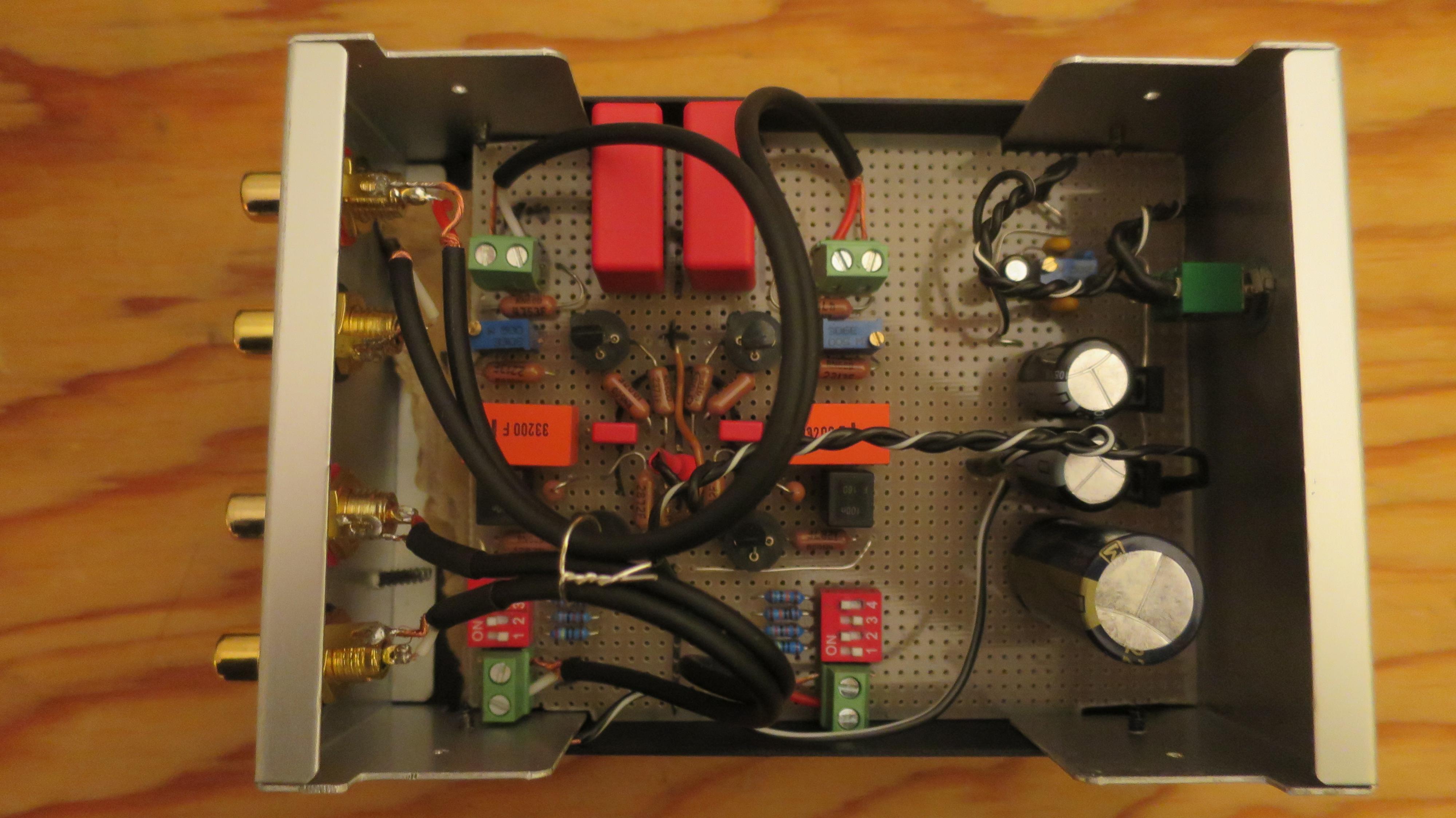
Thanks @all for your kind comments. Good that you only see the top of my perfboard ;-)
Hi Morfeus,
sorry i missed out all the new comments here.. I will draw the actual schematic next week, right now i dont got too much time..
I advise you to order your jfets at ebay at himmel-shop who ships matched quads of 2sk170 BL and GR from Germany. You can also ask him for the desired Id Values. For my version you will need something around 4.5 mA for the first stage and 7-9 mA for the second stage.
I will come back soon with the schematic. But mind that it fits best for low-output MM with 2.5 mV 1kHz@5cm/S. Good matches are Denon DL-110 or Nagaoka MP-110. Total Gain is around 42 dB at 1kHz - i have to admit that i still struggle to calculate the biasing of the jfets for lower gain. I thought i got it once but i cant reproduce it now..
@AddiDub
Do you have a schematic of your latest version?
Hi Morfeus,
sorry i missed out all the new comments here.. I will draw the actual schematic next week, right now i dont got too much time..
I advise you to order your jfets at ebay at himmel-shop who ships matched quads of 2sk170 BL and GR from Germany. You can also ask him for the desired Id Values. For my version you will need something around 4.5 mA for the first stage and 7-9 mA for the second stage.
I will come back soon with the schematic. But mind that it fits best for low-output MM with 2.5 mV 1kHz@5cm/S. Good matches are Denon DL-110 or Nagaoka MP-110. Total Gain is around 42 dB at 1kHz - i have to admit that i still struggle to calculate the biasing of the jfets for lower gain. I thought i got it once but i cant reproduce it now..
Sheffield TWANGers ! ... & ... Top Secret Wiring ...
.
" Hope this is not the case in Sheffield! "
Hi Malefoda
Strangely for a fairly ordinary English city, Sheffield has produced bucket loads of awesome mooodern music.
I shouldn't wonder if maybe 10% of my round-plastic hoard isn't somehow connected to it.
MAGIC !
- - - - - - -
" Good that you only see the top of my perfboard "
Hi AddiDub
I SEE !
Or rather I DON'T !!
So this is where all the solid-unobtanium wire & the MEGA $$$ BUCKS hi-end parts are huh ?
No wonder it's sounding so good.
I had thought the 'secret' design feature was your COOL circular-formation of resistors.
Make sure you check for fake unobtanium ...
... there are a lot of crooks about !
 Si.
Si.
t.S.E.c
.
.
" Hope this is not the case in Sheffield! "
Hi Malefoda
Strangely for a fairly ordinary English city, Sheffield has produced bucket loads of awesome mooodern music.
I shouldn't wonder if maybe 10% of my round-plastic hoard isn't somehow connected to it.
MAGIC !
- - - - - - -
" Good that you only see the top of my perfboard "
Hi AddiDub
I SEE !
Or rather I DON'T !!
So this is where all the solid-unobtanium wire & the MEGA $$$ BUCKS hi-end parts are huh ?
No wonder it's sounding so good.
I had thought the 'secret' design feature was your COOL circular-formation of resistors.
Make sure you check for fake unobtanium ...
... there are a lot of crooks about !
Si.t.S.E.c
.
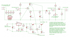
circuit drawing of my phono preamp
Hey guys and grrrls, i finally completed moving So after new years eve i found some time to draw one complete channel of my jfet preamp plus the power supply unit.
Remember there is nothing new in this circuit, it is just my most stable and best sounding version of around one dozen circuit variations build since 2016. Its just a try to do a proper documentation - and maybe get last hints for optimizing
The power supply unit is also documented in this drawing. Its a simple adjustable LM317 that lets you choose your usable Vcc from 18V to 22V. I found it very useful for fine tuning. After the LM317 circuit comes a capacitance multiplier, that Salas gave me: Pacific RIAA phono pre: failure!. The 2200uF output cap sits in the middle of my preamp board. The negative of the output cap is the central signal ground and is connected to the preamp chassis.
Any suggestions / critics / questions welcome
Hey guys and grrrls, i finally completed moving
So after new years eve i found some time to draw one complete channel of my jfet preamp plus the power supply unit.Remember there is nothing new in this circuit, it is just my most stable and best sounding version of around one dozen circuit variations build since 2016. Its just a try to do a proper documentation - and maybe get last hints for optimizing
The power supply unit is also documented in this drawing. Its a simple adjustable LM317 that lets you choose your usable Vcc from 18V to 22V. I found it very useful for fine tuning. After the LM317 circuit comes a capacitance multiplier, that Salas gave me: Pacific RIAA phono pre: failure!. The 2200uF output cap sits in the middle of my preamp board. The negative of the output cap is the central signal ground and is connected to the preamp chassis.
Any suggestions / critics / questions welcome
Attachments
Last edited:
- Status
- This old topic is closed. If you want to reopen this topic, contact a moderator using the "Report Post" button.
- Home
- Source & Line
- Analogue Source
- Pacific RIAA phono pre: failure!