Sakellogg, thanks very much!
I adjust my springs using a bubble like leveling device. it has a hole to fit over the spindle and the bubble is centered in a circle visible from the top. When I have them adjusted so that I can turn the table on and the bubble stays centered as it turns, its good.
Before the above procedure, I level the table itself first, using four screws that adjust each corner of my DIY wall mounted shelf. Once I verify ( using a short level) that the shelf as well as the top of the table are level, I get out the bubble spirit type level and do the above procedure.
Russellc
Resistor and Capacitor Load Switching
So, I'm on vacation to take care of my mom after back surgery and I had a chance between rehab visits to build the load switching circuit. It came out nice. I'm happy with it.
Si, the 1k load for the DL-110 is the way to go. From a cold start, one can tell that 47k is not correct or at least not optimal. More definition between notes and reverb that goes on forever.
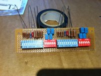
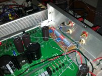
Here are two photos that tell the rest of the story.
The parallel resistors are 80k, 47k, 30k, 5k, 3.3k, 2.2k, 909, 300, 150 and 100 ohms. Caps are 100pF, 150pF, 220pF, and 330pF. I was going to add a 100k also but realized the switch is a 10 DIP and not 12, like I though was purchased. I can still add it permanently to the board, if needed.
5k, 3.3k and 2.2k get 1025 Ohms. 3.3k and 2.2k gets you 995 Ohms.
I went with 1025 and doubt 995 would be much different...but who knows!
By the way, the above are meter measured readings, not calculated.
Vince
So, I'm on vacation to take care of my mom after back surgery and I had a chance between rehab visits to build the load switching circuit. It came out nice. I'm happy with it.
Si, the 1k load for the DL-110 is the way to go. From a cold start, one can tell that 47k is not correct or at least not optimal. More definition between notes and reverb that goes on forever.
Here are two photos that tell the rest of the story.
The parallel resistors are 80k, 47k, 30k, 5k, 3.3k, 2.2k, 909, 300, 150 and 100 ohms. Caps are 100pF, 150pF, 220pF, and 330pF. I was going to add a 100k also but realized the switch is a 10 DIP and not 12, like I though was purchased. I can still add it permanently to the board, if needed.
5k, 3.3k and 2.2k get 1025 Ohms. 3.3k and 2.2k gets you 995 Ohms.
I went with 1025 and doubt 995 would be much different...but who knows!
By the way, the above are meter measured readings, not calculated.
Vince
Attachments
Personally, I have found (with respect to MC loading). the lower the capacitive loading the better in terms of top end air, space and transparency. However, it also shifts the character of the bass/mid a little and makes the circuit very much more susceptible to RF interference.
Although these capacitive changes are roughly analogous to the adjustment of tone controls the actual effect is not the same and implementing tone controls is a heavy handed, and inadequate, solution as far as I am concerned.
Although these capacitive changes are roughly analogous to the adjustment of tone controls the actual effect is not the same and implementing tone controls is a heavy handed, and inadequate, solution as far as I am concerned.
Last edited:
Way to go I N D E E D !
Boo JAH !
Hi Vince
Nice work on the loading board.
Thought you were going for a wi-fi connection at first...
...with all those little aeriels !
But no...
...fits in the Pearl as snug as a bug !
What with the Pearl PSU fix & the new 1K loading...
...sounds like the Denon should be living up to it's rep. now.
I like the sound of endless reverb...
...as long as it stops at the end of side A !
It will be interesting to hear what you think after listening to loadings either side of 1K as well.
It does from what others say seem to be 'the ball-park' on that cart...
...but you never know !
If you get the chance...
...how about some listening reports from 250r - 4k ( 4x in either direction ).
Could be interesting, especially on 'weird'pressings'...
...like ones where there are higher grooves / " ( less bass, right ).
Quite a handy, non-destructive tone-control.
Sticking a few caps across the terminals of the full-range drivers I have here...
...brings the treble down & makes 'em sound like SUBS !...
...albeit with a loss of sensitivity of course...
...but a good non-destructive speaker tone-control for sure.
Going slow @ Space Egg, but we're getting there.
Cheers.
Si.
Watch this space phono-fans, Vince is motoring at 78rpm !!!
Vince...you are the Indiana Jones of high-end loading-experiments.
Keep up the good work !
Cheers.
Si.
Vince: "capacitors.....why did it have to be capacitors?"
SI: " picofarads, lots of decimal places. You go first."
^ ?
Hi sakellog
Sorry dude, I don't get you...
...I love puzzles; but I can't work this one out !
A clue please ?
I did, as it happens, enter some of my RIAA calculations, as MY LOTTO #'s last week !
( didn't win though ! )
Cheers
Si.
Keep it coming Indiana !
I think the answer might be...
...5870000pF
&
...5790000pF
Mmmm...?
Sorry, my dumb humor.
Indiana jones
Raiders of the lost arc.
Just found the well of souls where the arc is.
Sala says the floor is moving.
Indy tosses a torch into the pit showing lots of snakes that indy is scared of and says...
Indy: "snakes.... Why did it have to be snakes?"
Sala rolls over and peers inside, says to indy...
Sala: " asps.... Very dangerous, you go first"
Looking back,i could see how it might look like a insult.
Not the case, truely. I'm just a dork.
Sorry.


So, I'm on vacation to take care of my mom after back surgery and I had a chance between rehab visits to build the load switching circuit. It came out nice. I'm happy with it.
Si, the 1k load for the DL-110 is the way to go. From a cold start, one can tell that 47k is not correct or at least not optimal. More definition between notes and reverb that goes on forever.
Here are two photos that tell the rest of the story.
The parallel resistors are 80k, 47k, 30k, 5k, 3.3k, 2.2k, 909, 300, 150 and 100 ohms. Caps are 100pF, 150pF, 220pF, and 330pF. I was going to add a 100k also but realized the switch is a 10 DIP and not 12, like I though was purchased. I can still add it permanently to the board, if needed.
5k, 3.3k and 2.2k get 1025 Ohms. 3.3k and 2.2k gets you 995 Ohms.
I went with 1025 and doubt 995 would be much different...but who knows!
By the way, the above are meter measured readings, not calculated.
Vince
Very nice build. But why no use the R20 for loading? Is there any reason?
.Too many pF's for the Denon...
...don't try this at home folks !
GOOD for the speakers Indiana...
Si.
"shut up Santa...yer ol' duffer"
I have many those (the same) capacitors of various capacitance of each.
.
Answers may often be found in the manufacturer's data sheet for the cartridge in question.Jenyok said:Some questions about MM and MC cartridges.
Some questions about MM and MC cartridges.
.
Output voltage for MM cartridge from MIN to MAX volts (mVolts, mkVolts) ?
Output voltage for MC cartridge from MIN to MAX volts (mVolts, mkVolts) ?
For various models of MM and MC cartridges.
MCs are typically 0.3milliV to 0.5millV ... occasionally outside this range so can be 0.1miiliV to 0.6milliV.
MMs are typically 5milliV - but can be as 4milliV or even as low as 1milliV.
Andy
.MCs are typically 0.3milliV to 0.5millV ... occasionally outside this range so can be 0.1miiliV to 0.6milliV.
MMs are typically 5milliV - but can be as 4milliV or even as low as 1milliV.
Andy
Thanks mate.
.
- Status
- This old topic is closed. If you want to reopen this topic, contact a moderator using the "Report Post" button.
- Home
- Source & Line
- Analogue Source
- MC and MM Resistor and Capacitor Loading