Wondering if someone could take a look at my Roberts Model 50 receiver schematic and be able to tell me what voltage the stereo indicator lamp should be and explain how that part of the circuit works.
I believe it should only light the lamp when a FM "stereo" station is dialed in. There is no value listed for the lamp and the existing one was burned out and the socket badly corroded. The lamp socket sits behind a small red jewel lens on the front panel.
There are also "dial" lamps which ARE listed in the schematic (3.2V x 6) but those are powered from a separate 3.2VAC winding from the power transformer and working fine.
The indicator lamp also has a different P/N in the service manual than the dial lamps but of course the P/N doesn't give you any clue as to the voltage or current.
So I'm pretty sure the stereo indicator lamp is a different voltage and current.
There is a voltage listed in the closeup schematic where the "star" symbol is shown (8.4V) and it is on one side of the indicator lamp socket but when I put a meter across the socket (no lamp installed) it measures 24V all the time. No change in voltage as I move the dial around to a stereo signal.
The two transistors Q13/14 look like what switches the lamp on when "stereo" is detected, but again I'm not very good at figuring out circuits and starting to think there is something wrong in that portion of the circuit.
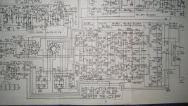
I've attached a full schematic and then a closeup of the stereo indicator section.
Hoping someone can look at those and help me out....Thanks for any help and expertise you can offer!
I believe it should only light the lamp when a FM "stereo" station is dialed in. There is no value listed for the lamp and the existing one was burned out and the socket badly corroded. The lamp socket sits behind a small red jewel lens on the front panel.
There are also "dial" lamps which ARE listed in the schematic (3.2V x 6) but those are powered from a separate 3.2VAC winding from the power transformer and working fine.
The indicator lamp also has a different P/N in the service manual than the dial lamps but of course the P/N doesn't give you any clue as to the voltage or current.
So I'm pretty sure the stereo indicator lamp is a different voltage and current.
There is a voltage listed in the closeup schematic where the "star" symbol is shown (8.4V) and it is on one side of the indicator lamp socket but when I put a meter across the socket (no lamp installed) it measures 24V all the time. No change in voltage as I move the dial around to a stereo signal.
The two transistors Q13/14 look like what switches the lamp on when "stereo" is detected, but again I'm not very good at figuring out circuits and starting to think there is something wrong in that portion of the circuit.
I've attached a full schematic and then a closeup of the stereo indicator section.
Hoping someone can look at those and help me out....Thanks for any help and expertise you can offer!
Attachments
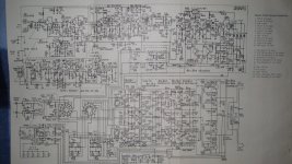
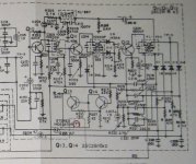
Q13 and Q14 together form a Schmitt trigger, but this uses the stereo lamp as part of the circuit so it won't switch with the lamp open circuit. The 8.4V rail seems to come from a resistor near Q29/Q30 in the PSU but the bottom of this part is cut off your diagram.
My guess is something like 8V 40mA might work. Alternatively, an LED in series with a resistor (470-1K?)). The resistor would get hot so use 2W?
My guess is something like 8V 40mA might work. Alternatively, an LED in series with a resistor (470-1K?)). The resistor would get hot so use 2W?
As above but I would suggest an LED in series with a suitable resistor (many LED's need 1ma or less) and then a parallel resistor across the lamp socket to get the correct current draw so the circuit works OK. The Schmitt trigger just prevents the bulb from being in an indeterminate state or from flickering. Its either on or off... in theory ")
That MPX decoder is clever, I like it.
24V is a little worrying, as the circuit implies that 8.4V is what should be available there, so I would have a look at the power supply before replacing the lamp.
The circuit works as follows: stereo multiplex is applied to the buffer amplifier Q10, and the signal split, with one path across the top filtered by a parallel tuned circuit to remove the 19Khz pilot tone and a second via the tuned transformers and Q11,12 tuned to a sharp 19Khz.
This path inclued a frequency doubler D9,10 so the drive to Q12 is at 38Khz and at sufficient level to saturate the diodes following the final transformer, the centre tap of which has the MPX signal minus the 19Khz carrier presented to it.
The effect is that the switching diodes and transformer both demodulate the 38Khz DSB S component and perform the addition/subtraction to give L & R.
There is an ALC loop around the 19Khz chain (Reduces the effect of multipath), from the emitter of Q12 to the emitter of Q11, and it is this voltage (which rises when the 19Khz stereo pilot is present) that drives the schmitt trigger.
HTH.
Regards, Dan.
Q13 and Q14 together form a Schmitt trigger, but this uses the stereo lamp as part of the circuit so it won't switch with the lamp open circuit. The 8.4V rail seems to come from a resistor near Q29/Q30 in the PSU but the bottom of this part is cut off your diagram.
My guess is something like 8V 40mA might work. Alternatively, an LED in series with a resistor (470-1K?)). The resistor would get hot so use 2W?
Well that's interesting...I've used Schmitt triggers in digital chip form, but guess I've never seen a discrete transistor version. I guess I was partially right about them switching! Just a little more clever than I thought...
Thanks to all for your help and explanations...
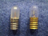
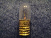
I attached the bottom part of the schematic and a close up of both types of lamps.
The (frosted) left lamp is one of the dial lamps "3.2V 0.16A".
The (clear) right lamp is the indicator lamp "6V 0.05A" I think!.....
The "6" is hard to see and all these lamps were solder blobbed into their sockets, so by the time I got the solder wicked off and unscrewed them...it was hard to read the markings!
I thought because of the 24V reading across the ind. socket maybe it was a "26V" marking on that lamp!
But if "8V 40mA" makes more sense and also needs to be "in circuit" then the "6V 0.05A marking makes much more sense than "26V".
So that is good....I think 6-8V 40-50mA is what I need to find.
Like Dan mentioned I thought there was also something wrong with that 8.5V power supply location so I lifted and checked R502 (400ohm 2W) and R503 (2.2Kohm 1/2W). They both read correct resistance and C507 is a new replacement cap.
I measured 30V at the top of R502, but 24V between R502/503 (across C507) but that was without the lamp installed!??
So I'm still confused if there is something wrong with the power supply, or I just need to get a lamp plugged into that socket and the voltage will be correct?
I'll see if I can find an LED and 2W resistor to test it, but I would eventually like to get a replacement incandescent...
Thanks Dan for that explanation of how the stereo signal is stripped out and detected. Tuner schematics are pretty intense and confusing for me. But I like to learn something new everyday!
I've managed to get this 1963 Roberts receiver back up and running very well, and these lamps are the last phase of repair.
So far I haven't touched anything in the tuner at all. It does seem to work fine.
There are a few electrolytic caps on the tuner board that I could replace, but haven't. Do you think that would be a good idea?
Thanks for all your help and suggestions!
Attachments
Small bulbs are still available... not sure on the physical sizes though,
F017 - -- - 6V LES BULBS - PACK OF 2 | CPC
Your Search Results | CPC | Results
originality can be good sometimes.
F017 - -- - 6V LES BULBS - PACK OF 2 | CPC
Your Search Results | CPC | Results
originality can be good sometimes.
Hmmm... R212 and R227 and 24 volts and a 6 volt bulb doesn't sound right. If the resistors were a factor of 10 bigger then maybe.
Something doesn't ring true here with the circuit and the bulb. There is a 24 volt supply shown on the diagram....
Could the bulb be non original and someone has swapped it for the wrong rating ?
Something doesn't ring true here with the circuit and the bulb. There is a 24 volt supply shown on the diagram....
Could the bulb be non original and someone has swapped it for the wrong rating ?
Remember your bulb has R212 and R227 in series with it so they will drop some voltage.
Are we going to try and work it out as a series chain or just do it empirically ?
Thanks Mooly for the link...I'm in the US so I'm hoping to find something at MCM Electronics or Rado Shack that's close and cheap shipping!..lamps can be inexpensive but the shipping is what kills you in cost!
I'm hoping that is what's going on with the lamp being in series there and not some problem with that part of the power supply. Everything else on this unit is working and has correct voltages.
I can check R212 and R227 to be sure they are not open.
If there's a way to know that's why the voltage is high or you can do the calculation that would be a big relief and save me burning out a bulb or LED testing.
I'm not very good at doing the math...
It works out spot on for a 6 volt bulb.
You have 30 volts flowing through 400 ohm + 22 ohm + 15 ohm + x (the bulb). The bulb is 6 volt at 50 ma so that implies a resistance of 6/0.05 which is 120 ohm.
So we have 30 volts across 557 ohms which gives 53 ma. R503 (a 2K2) also shunts across the bulb + R212/227 chain.
So including that gives a 400 ohm and 147 ohm (equivalent) which gives a current of 55 ma total on 30 volts. That leaves 8 volts at the junction of the 400 and 2K2 resistors and 8 volts across the bulb and R212/227 is now 50.9 ma. Loose a few 10's of millivolts across the saturated transistor and you have 50 ma as near as makes no difference
So it works out. You 6 volts and 50ma flowing in the bulb. Now what if the mains goes up or down
I do have some #40 lamps here that are:
6.3 Volt 0.15 Amp 0.945 Watt T3-1/4 Miniature Screw (E10) Base, 0.52 MSCP C-2R Filament.
Could I use one of those for the indicator lamp without harm?
Another question.....could I also use those #40 6.3V .15A lamps for the dial lamp replacements which were originally 3.2V .16A bulbs.
Those dial lamps have a separate transformer winding which is listed as 2.8VAC.
Would that be too high of a voltage or damage that part of the transformer?
A 0.15A stereo lamp won't glow very much but it probably won't do much harm. Because of the series resistor the lamp current rating is actually more important than the voltage, as it almost has a constant current supply.
Similarly for 6.3V lamp on a 2.8V supply, although here the voltage rating matters most.
Similarly for 6.3V lamp on a 2.8V supply, although here the voltage rating matters most.
A 0.15A stereo lamp won't glow very much but it probably won't do much harm. Because of the series resistor the lamp current rating is actually more important than the voltage, as it almost has a constant current supply.
Similarly for 6.3V lamp on a 2.8V supply, although here the voltage rating matters most.
Thanks DF96, I just didn't want to ruin anything. I apologize for my ignorance with this, but substituting or changing things, I worry about burning something else up in the process. Getting these dial lamps and stereo indicator light all working isn't a big deal but it would be fantastic if I can replace them with what I have on hand and everything works!
I'll give them a try and see if the dimmer light output is OK visually.
The indicator lamp has a black tube sleeve around it and sits right behind a tiny red jewel on the face plate. So that might not be that noticeable.
There are 5 dial lamps that sit in front of the plastic dial face and then the 6th lamp backlights a little signal strength tuning meter (which works).
Again those might not be that noticeable being a little dimmer once I get the face plate all back together. Even if they are slightly dimmer it's certainly better than nothing at all.
When I opened this up to fix a bad channel 6 out of those 7 lamps were out.
Also the original 6 dial lamps were frosted and these #40 are clear so maybe that will help!
BTW, I found the filament resistance of those #40's which is 39.5 ohms if that helps.
Thanks again for all of you helping me with this!
It works out spot on for a 6 volt bulb.
You have 30 volts flowing through 400 ohm + 22 ohm + 15 ohm + x (the bulb). The bulb is 6 volt at 50 ma so that implies a resistance of 6/0.05 which is 120 ohm.
So we have 30 volts across 557 ohms which gives 53 ma. R503 (a 2K2) also shunts across the bulb + R212/227 chain.
So including that gives a 400 ohm and 147 ohm (equivalent) which gives a current of 55 ma total on 30 volts. That leaves 8 volts at the junction of the 400 and 2K2 resistors and 8 volts across the bulb and R212/227 is now 50.9 ma. Loose a few 10's of millivolts across the saturated transistor and you have 50 ma as near as makes no difference
So it works out. You 6 volts and 50ma flowing in the bulb. Now what if the mains goes up or down
Just to see if I could actually do the math I followed your math and did the re-calculation using the 6.3V 159mA lamp which has a resistance of approximately 40ohms. (39.6)
So here goes:
400+22+15+40=477ohms @ 30V= 63mA.
22+15+40= 77 in parallel with the 2200=74ohms (I think that's correct)
The 400ohm would now have 25.2V leaving only 4.8V at the junction.
4.8V across the bulb + series resistors is 62mA.
minus a few 01th for transistor about 61ma.
Which would be only 2.4V at the bulb!!
That seems pretty low....hence the dimmer bulb, but nothing harmful!
Of course I don't know if I got that all correct.
I guess if it doesn't light up I'll have to find the correct 6V 50mA lamp.
Now on the dial lamps I have the same resistance of 39.6ohms x 6 in parallel = 6.6ohms with a 2.8VAC supply = 420mA
The original lamps were 3.2V 160mA, so that's 20ohms x 6 = 3.3ohms = 850mA.
So those will also be dimmer, but not harmful.
I'll just have to see if they work out and if not get all the right lamps!
Please correct me if you see errors in my math or conclusions.
This was a great learning session for me and actually a fun exercise....
Thanks for all the help!
You got it correct
The LED and resistors would still be a perfect solution for the stereo indicator apart from originality. Fitting a 120 ohm in place of the bulb would give the correct DC conditions. With 6 volts across 120 ohms we then add an LED and series resistor across that 120 ohm. The LED will have a volt drop of around 2 volts (give or take) leaving 4 volts to lose across its series resistor. So that would work out at around 4000 ohms allowing 1ma for the LED. We can't put an absolute value on it because it depends on the LED and how bright you want it. So you could end up with as high as 10K or as low as say 400 ohms.
The important thing with the dial lamps is that they don't draw more total current when on than the originals. LED's used here may not look right and it could be difficult to get the correct even illumination pattern. Another problem is these lamps running on AC. To use LED's you would need to provide protection from reverse voltage (by using a diode). Even then we have another problem... you would probably see the LED's flicker due to the AC. We can get around that one by arranging the 2.8 volt supply to become a DC rail and powering the LED's normally. Its easy but loses totally the originality.
(you probably know this but you can't measure filament resistance on a cold bulb as it will be very low indeed... just in case you found some old bulbs)
I don't remember exactly, but I recall that the 60Hz flicker would be indistinguishable by the human eye. Not unlike the 60Hz refresh rate of the old NTSC standard(?). I seem to remember the threshold being something like 40Hz or 28Hz.
If I remember later today I'll try it with an LED and generator. If you look "out of the corner of your eye" rather than directly at such a light source then flicker is more obvious.
- Status
- This old topic is closed. If you want to reopen this topic, contact a moderator using the "Report Post" button.
- Home
- Source & Line
- Analogue Source
- FM Stereo indicator lamp in Tuner circuit