Hi All,
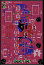
I've been reading these forums for the past few days. I've come up with a schematic and PCB based on the preamp design based on the TI application note "Application Note 1651 Keeping Up with the Expanding Demands of
High-Performance Audio". http://www.ti.com/lit/an/snaa046/snaa046.pdf
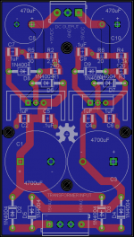
I also quickly put together a board for a simple LM317/337 +/-15V power supply.
Attached are the files.
I've been reading these forums for the past few days. I've come up with a schematic and PCB based on the preamp design based on the TI application note "Application Note 1651 Keeping Up with the Expanding Demands of
High-Performance Audio". http://www.ti.com/lit/an/snaa046/snaa046.pdf
I also quickly put together a board for a simple LM317/337 +/-15V power supply.
Attached are the files.
Attachments
 Moved to Analog Source. (Most phono stages are located here.)
Looks pretty good,let us know your test results and listening impressions.
May want to place some capacitors across the rectifier diodes to suppress the diodes switching transients.
Only one 100n cap at the LM317/337 inputs is required.
Do not rely on solder mask as an insulator for your heatsinks. Not sure if the will be sitting on the tip layer of the PCB.
Use 1% resistors for the RIAA equilization network & 2% film caps
I do not see any 100n/X7R bypass caps close to the supply pins of the opamps? These are necessary!!
Regards
Rick
- Status
- This old topic is closed. If you want to reopen this topic, contact a moderator using the "Report Post" button.