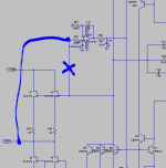
You need to connect the servo to the output of the buffer, otherwise vgs (when connected to the input (as shown)))) of the fet's is used to create an imbalance in the mirrors. And if you insist, the experiment (that fails / will fail) will be to switch it to the buffer input (and back (very fast)).
I see what you are saying.
Let me correct it then!
You need to connect the servo to the output of the buffer, otherwise vgs (when connected to the input (as shown
Edit: Wrong I was. I should have said that the vgs of the fet's would be translated in a output offset if the servo-input is connected to the buffer input.
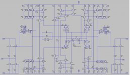
See picture (telling a 1000 words)
[And yes, I have seen nicer drawings]Attachments
Last edited:
See picture (telling a 1000 words)
Fine, I don't understand why the latter wouldn't work, since the output resistor will restore the output offset to 0 (simulation shows that it properly works).
Servo will push 0V at the gate, Source of the Jfet will go roughly down to -0.2V and then other side of the resuistor will cancel the offset restoring it to 0V.
Can you tell me where this reasoning fails??
EDIT: I have the prototype running that way and output offset is about 1mV!
Last edited:
I would include the Calvin buffer on the test PCB.
The InterFet type can then be build external.
However good the InterFet sounds i think that the Calvin buffer has better technical data.
The InterFets could also being used in a Calvin arrangement.
yeah it actually makes more sense.
It is easier to build that buffer vs Calvin so having it on a PCB will help development.
Good point!
True instead of the K389 we can use the IF3602 since it proved to have a superior sound.
Can you tell me where this reasoning fails??
EDIT: I have the prototype running that way and output offset is about 1mV!
It (probably) fails nowhere, but connecting to the low impedance output will be better than to the high impedance input, also it will remove the 1mV, and there is no chance that component tolerances, input voltage differences (vgs), aging, temp, and more factors will ever result in (any form of) output offset.
Last edited:
It (probably) fails nowhere, but connecting to the low impedance output will be better than to the high impedance input, also it will remove the 1mV, and there is no chance that component tolerances, input voltage differences (vgs), aging, temp, and more factors will ever result in (any form of) output offset.
ok now I agree with this

Yes, we can try that.
ok sounds good. I will update the schematic with Calvin buffer using IF3602 on driver.
EDIT: I have the prototype running that way and output offset is about 1mV!
ok now I agree with this
Wow, finally
The main point is, we are looking for the best solution, not for one that works (only) Wow, finally
Yes we are looking for the best technical but mostly sounding solution.
For instance I have checked the bias on the IF3602 and it is lower than what I thought with only 16mA.
In this case however is not so high, the big difference in sound was made by part itself!
In short, maybe this buffer with this part might not be the top or the best in term of specs, nevertheless if it will end up sounding better than Calvin for instance, I would have no indecisions in choosing this one over the latter although it has better specs.
Just to give you a background on my philosophy in this design and I think that here we all agree on that which is pretty amazing.
I believe that the most important part is that you have same beta in all mirror transistors, making quad arrays a very good choice, in some of my paradise variation i have used 3906/3904 quads with good results. I have always used about 120 ohms as degeneration, this is solely based on experience. In power-amps with larger currents I use smaller, in order not to loose to much rail voltage.
I believe that the most important part is that you have same beta in all mirror transistors, making quad arrays a very good choice, in some of my paradise variation i have used 3906/3904 quads with good results. I have always used about 120 ohms as degeneration, this is solely based on experience. In power-amps with larger currents I use smaller, in order not to loose to much rail voltage.
makes total sense.
What is the manufacturer for the semiconductors you are recommending?
I would like to check the specs out.
A dip8 can do 1W.
oh really? Didn't know that.
I also think 120 Ohm is about optimum. Making it much smaller will amplify the noise of the mirror, not a big problem in power amps but here i think it is critical not to worsen the noise of the input stage. Making it bigger makes the output impedance of the mirror higher
and yes, it will eat up some dynamic range. The output impedance of this cascoded mirror is already sky high so i think we are fine.
and yes, it will eat up some dynamic range. The output impedance of this cascoded mirror is already sky high so i think we are fine.
- Status
- This old topic is closed. If you want to reopen this topic, contact a moderator using the "Report Post" button.
- Home
- Source & Line
- Analogue Source
- Masterpiece