I would like to do a FFT Distortion analysis like the one I see on Paradise's thread.
Can anybody here nudge me in the right direction?
I had download a little while ago a little script with a block but it didn't seem to offer the same resutls other's were getting.
Thanks.
Can anybody here nudge me in the right direction?
I had download a little while ago a little script with a block but it didn't seem to offer the same resutls other's were getting.
Thanks.
Last edited:
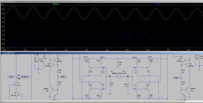
here you go....
Isn't it really beautiful? So far so good...see if what I have studied works in practice too...
It may be, but the initial offsets cancel, I would like to see both starting at an positive (or negative) offset
now one starts at a positive and the other at a negative offset.It may be, but the initial offsets cancel, I would like to see both starting at an positive (or negative) offset
I tried all 4 combinations and I get the same exact result.
To this scheme it doesn't matter if either side is starting positive or negative or same offset, it will zero-it-out in common-mode.
Maybe I am missing something and I can try now to really mess things up trying to make the common-source different and see what happens then.
I will post shortly.
here is the flaw....
if the source resistance is made a little different, which could easily account for tolerance on the IDss of the Jfets, that is where the common mode behaviour of the servo pops up again.
I would also like to trim both source resistance to compensate for 2nd harmonic distortion due to asymmetry on the transconductance curve between p and n channels Jfets.
I am wondering if that same trimming can be used to correct the common mode offset and if the offset would stay down two zero once trimmed or it would wonder due to the thermal unstability of this Jfet's family i.e. not useful tempco available operating point?
Any advice would be surely very appreciated.
Attachments
I have created the prototype and tested the Servo.
Unfortunately servo isn't working so it is impossible to perform any kind of test and/or listening tests.
If anybody here can take it up a notch and throwing some possible solutions that can be tried, this would help moving this on...
Unfortunately servo isn't working so it is impossible to perform any kind of test and/or listening tests.
If anybody here can take it up a notch and throwing some possible solutions that can be tried, this would help moving this on...
I have created the prototype and tested the Servo.
Unfortunately servo isn't working so it is impossible to perform any kind of test and/or listening tests.
If anybody here can take it up a notch and throwing some possible solutions that can be tried, this would help moving this on...
Maybe the easy way out is, use 2 servo's for now, when this functions then give it some more thought-time and update (to one servo or any other solution). I cannot spend much time on this (at the moment), so I will try to follow and comment (as I see needed/wanted or prudent) but that is all for the foreseeable time
I am not trying to be a pain, but would it be easier and perhaps more educating to start with simpler layouts, even balanced, and work up. This is a very complicated design and even with the help of many others, it may be too much of a first try. Often in working from simplr to more complex designs, you find /learn things that will help improve the final product anyway. Yo may even find the simpler version is preferred, as you will have listened along the way. Just a suggestion.
No pain, don't worry!
The circuit is very simple if you look at it. Some of the circuitry is needed to keep the servo away from, the path and the rest purely to increase gain but doen't have any additive extra stage to it.
It almost can be seen with a 1 stage gain plus simple buffer.
The problem here is to design a working servo for balance operation.
I am not an expert of servos but if you have any suggestion on simpler topology we can start from I would be more than happy to consider it and start with that.
I like the approach bottom top anyway...
Buzz,
I think that this thread is Stefano's and his original post was of a design that was his. He was attempting if I say this right to build his ultimate circuit implementation for a two-section RIAA stage and this was his baby. He is just letting those who want to to contribute to that level of design or just to watch the build. He said this was not going to be a group project in the first post. If you want to build it you are on your own for a board or anything else. If he gets this right and is nice enough he may give us the artwork to go make our own boards and try and build one ourselves.
I think that this thread is Stefano's and his original post was of a design that was his. He was attempting if I say this right to build his ultimate circuit implementation for a two-section RIAA stage and this was his baby. He is just letting those who want to to contribute to that level of design or just to watch the build. He said this was not going to be a group project in the first post. If you want to build it you are on your own for a board or anything else. If he gets this right and is nice enough he may give us the artwork to go make our own boards and try and build one ourselves.
What? He has clearly stated that it is an open project and has asked for help. I was simply pointing out that reducing complexity might help him achieve his final goal. More simply stated, strip it down to basic structure and work back up. It was just a suggestion, that he decided not to heed. No harm done. Just a suggestion.
What? He has clearly stated that it is an open project and has asked for help. I was simply pointing out that reducing complexity might help him achieve his final goal. More simply stated, strip it down to basic structure and work back up. It was just a suggestion, that he decided not to heed. No harm done. Just a suggestion.
Yes, you two are both right. I would like to achieve the best and I am sharing my solutions to those who are experts to improve it and work it out.
If everything works fine, the details to build it will be here on these pages.
Starting from a simpler circuit to work the way up if the circuit MasterPiece-R5 can't be worked out due to some reason, could be a possibility.
I am going to change simulation back to 2 servos to see if the approach works (I remember that even two servos with this arrangement could possibly not work)
I will post back shortly I have other tasks I need to work out first here at work
Ok, here it is finally.
It was a lot of work, more than what I thought it was going to be to get both combination of gain and DC offset right.
The way the schematic was drawn in Rev.5 wouldn't allow not even 2 separate servos to work properly unless the differential feedback was re-stored.
With this approach instead (a little bit of symmetric differential feeback and common mode feedback as well to allow common reference for both halves), at least theoretically, the offset is guaranteed both absolute and relative with only minor loss of gain (went down to 60dB but it can be eventually brought up by either tweaking the network again or by paralleling more FET).
Please feel free to comment.
I will probably test this tonight hopefully and I will let you all know if it works in practice as well and I am confident we can knock the servo down to a single one and hopefully people here will start cheaping in a bit more .
It was a lot of work, more than what I thought it was going to be to get both combination of gain and DC offset right.
The way the schematic was drawn in Rev.5 wouldn't allow not even 2 separate servos to work properly unless the differential feedback was re-stored.
With this approach instead (a little bit of symmetric differential feeback and common mode feedback as well to allow common reference for both halves), at least theoretically, the offset is guaranteed both absolute and relative with only minor loss of gain (went down to 60dB but it can be eventually brought up by either tweaking the network again or by paralleling more FET).
Please feel free to comment.
I will probably test this tonight hopefully and I will let you all know if it works in practice as well and I am confident we can knock the servo down to a single one and hopefully people here will start cheaping in a bit more
.Attachments
Ok, now it gets interesting. Good luck.
Tonight and tomorrow I am making the paradise to start listening to it...also because I have been out of a phono stage for quite some time now
...also by having it I will have a reference to listen to.The only variant to it will probably be that instead of bjts I will use jfets not sure yet.
If you decide to use jfets in your paradise, will you be droping the big EL caps ?
Is it possible to use just half of Masterpiece 6 as a unbalanced amp ?
What is your reasoning behind using R68 R79 as 22ohms... do you need more current there ? (Or is it because the buffer is working at +-35v here) ?
Is it possible to use just half of Masterpiece 6 as a unbalanced amp ?
What is your reasoning behind using R68 R79 as 22ohms... do you need more current there ? (Or is it because the buffer is working at +-35v here) ?
Last edited:
I have built the paradise using Jfets and without the big caps... grainy and muddy compared to the Bipolar's, they have a warmer tone, but lacks the crisp and dynamic, so dull an warmer is what you get.
Sorry I don't understand the current mirror around the current source, it's a dead short, no need for that in the way you have designed this, only reason it works is the current running to and from the ground. your Jfets are running on IDSS.. In simulation that would sort of OK'ish as they are all the same...REaL-life..??
Sorry I don't understand the current mirror around the current source, it's a dead short, no need for that in the way you have designed this, only reason it works is the current running to and from the ground. your Jfets are running on IDSS.. In simulation that would sort of OK'ish as they are all the same...REaL-life..??
Last edited:
Thank you for your input MiiBI have built the paradise using Jfets and without the big caps... grainy and muddy compared to the Bipolar's, they have a warmer tone, but lacks the crisp and dynamic, so dull an warmer is what you get.
PS: Remenber my PM ?
- Status
- This old topic is closed. If you want to reopen this topic, contact a moderator using the "Report Post" button.
- Home
- Source & Line
- Analogue Source
- Masterpiece