Why are the 2SJ74 connected to the cascodes with the sources ?
ok that is probably a glitch on the schematic. both J74 and K170 are connected to the cascode through their drains.
I have to study that complex circuit in detail but i also have to prepare for a show in Venthoven this weekend. I will jump in when i find the time.
thanks, looking forward to hearing back from you.
this is getting very complex... Why did you use two circuits in series ? Is is a split riaa ?
Split indeed. The servo alone is looking bulkier than my entire phono pre
")
this is getting very complex... Why did you use two circuits in series ? Is is a split riaa ?
Thanks for your post.
I used two circuit in series to be able to split RIAA, having more control on the precision and split the "burden" on each stage and I wanted to operate each stage at lower gain
Split indeed. The servo alone is looking bulkier than my entire phono pre
ahahah that made my day! ahahaha!!
Anyway yeah the servo is a little bulky, but remember you are trying to correct the differential signal so you need the inverting stage to be able to do it.
alternatively you can
1) use coupling caps (which is not the best soluition IMHO)
2) use two single sevos.
This phono is not going to be a simple little kit but it is hopefully going, with the help of Mr. Joachim and other experienced people on the forum here, to be a very fine balance design.
This way you add a lot more parts in the signal path... do you believe that is a good idea ?Thanks for your post.
I used two circuit in series to be able to split RIAA, having more control on the precision and split the "burden" on each stage and I wanted to operate each stage at lower gain
What are the benefits of doing the 50hz -500hz shelving in the first stage and than the low pass filter on the second besides beeing more acurate in the shelving itself ?
PS:
I can not read the schematic values... would you care to post a PNG pic file with more resolution ?
I would like to play with your values... just for learning purposes
Last edited:
Thanks for your objection.
The reason is:
1) more control and more accuracy on the shape of the RIAA
2) each gainstage operates at a lower gain which gives you benefits in terms of both harmonic distortion and frequency response
3) No use of Big electrolytic capacitor on the signal path (whether in series or parallel)
Let me know your thoughts.
So to avoid the big EL you want to use lower gain.... That is a very good reason.
I never used a split riaa because using one more amplifying stage I would invert signal (because I use SE single transistor amplifiers).
Thank you for your input Stefanoo.... can you post a finer pic ?
I never used a split riaa because using one more amplifying stage I would invert signal (because I use SE single transistor amplifiers).
Thank you for your input Stefanoo.... can you post a finer pic ?
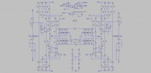
For everybody's enjoyment, here is a balance version of the paradise wrapped up for you with values and everything.
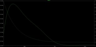
The relative RIAA's accuracy is attached as well.
I lowered the "bootstrap"'s cap values as it still yealds to a very precise shape
As it can be seen it doesn't use Standard values for the RIAA and getting custom made values for this is going to be pretty hard only with a group by they probably can be had at a good price.
Now I or anybody here with some skill can obviously build this.
What I have objected with this, is the use of high value electrolytic capacitors.
In my experience anytime such a part is introduced whether on coupling or on feedback or on shaping pole to compensate thermal they have constituted a deterrant effect on sound quality.
The effect on the sound is something I can clearly remember for as bad as it sounds compared to different approach.
This is the only objection I have with this topology.
In order to overcome that, I feel you need two gain stage unless we can come up with some alternative to it.
the servo works differentially so you can't simplify it unless you decide to use coupling cap but I guarantee you it is not going to sound as good.
Other aspect regarding the servo is that differential voltage is going to be perfectly zeroed out, but my concern is that absolute offset my wonder around and maybe another fix there might be needed.
If we can come out with a simple -one gain differential stage approach- I am obviously in favor of that over the 2 stage just to make this clear: I am not in favor of unnecessary complexity.
However, custom caps will be needed for this approach.
My intent here is to bring all the know-how of this forum to build the best of the best or like Joachim wants to call it: the MasterPiece.
Attachments
So to avoid the big EL you want to use lower gain.... That is a very good reason.
I never used a split riaa because using one more amplifying stage I would invert signal (because I use SE single transistor amplifiers).
Thank you for your input Stefanoo.... can you post a finer pic ?
Thank you very much for your comment.
In attachement the schematic for the balance MasterPiece and the Balance Paradise.
Attachments
Using non standard cap values for the riaa is not a problem as we can always (and I always do) build the most acurate possible with parallel combinations.
Removing the bootstrap caps seems a very logical thing to do also (we are using servos to eliminate coupling caps so we should also avoid the EL in the signal path)
What should be the max possible gain with this last schematic without the EL caps ?
Removing the bootstrap caps seems a very logical thing to do also (we are using servos to eliminate coupling caps so we should also avoid the EL in the signal path)
What should be the max possible gain with this last schematic without the EL caps ?
Thank you very much for your comment.
In attachement the schematic for the balance MasterPiece and the Balance Paradise.
Thank you so much
They seem quite similar apart from more trannies on the input....
Care to comment on your choices ?
Using non standard cap values for the riaa is not a problem as we can always (and I always do) build the most acurate possible with parallel combinations.
Removing the bootstrap caps seems a very logical thing to do also (we are using servos to eliminate coupling caps so we should also avoid the EL in the signal path)
What should be the max possible gain with this last schematic without the EL caps ?
I think you get to a low 45dB or something without EL cap.
Rember one thing, paralleling caps on the RIAA is not going to be ideal solution.
Best would be to have 1 cap.
Especially paralleling is often done with different values and that yealds to the worse result.
I am just sharing information I had talking to a person who is on the capacitor's manufacturing for audio.
I also experimented with that and it only confirmed his words.
Thank you so much
They seem quite similar apart from more trannies on the input....
Care to comment on your choices ?
yes, on the one gain approach, you need as muich gain as possible to get up to 62dB and mantaining the same network for the RIAA.
Also since all the Trans-RIAA is going to be there, you also need more current capabilities on both FE and VAS stage to drive it at high frequency.
On the other hand, also experimented with this, if from one side you get more benefit by paralleling more JFETs in terms of a bit darker background, from a sound standpoint, 4 paralled trannies yeald to a duller sound than a pair in front with a tad more degeneration and more gain distribution.
I have accumulated several years of experience in phono design and listened to a lot of solution and I would like to share the little knowledge I have and join it with the "monsters" here to create something top notch if possible and if people are interested and it is a honor for me to have Joachim join us as soon as he is back from his trip.
What is the gain difference between the paradise balanced and the masterpiece you posted in pdf ?
Maybe we could use a 45db and a SUT... that would go to around 70db
something I haven't experienced with is SUT. I firmly believe that there shouldn't be any EL of Film cap on the signal path and especially not a transformer on it.
this is just my personal thought.
There is no difference in gain between the SE and BAL paradise except that you get 6 more dB on balance which equals the SE on the straight Paradise design.
So for instance if Paradise has 62dB gain @1KHz, the BAL will have 56sB SE and 62dB BAL.
I think you get to a low 45dB or something without EL cap.
Rember one thing, paralleling caps on the RIAA is not going to be ideal solution.
Best would be to have 1 cap.
Especially paralleling is often done with different values and that yealds to the worse result.
I am just sharing information I had talking to a person who is on the capacitor's manufacturing for audio.
I also experimented with that and it only confirmed his words.
Maybe not the ideal solution but when you can not "trim" your caps by unwinding them, it is much better than using only aproximate values for the riaa calculated values.
- Status
- This old topic is closed. If you want to reopen this topic, contact a moderator using the "Report Post" button.
- Home
- Source & Line
- Analogue Source
- Masterpiece